

Abstract
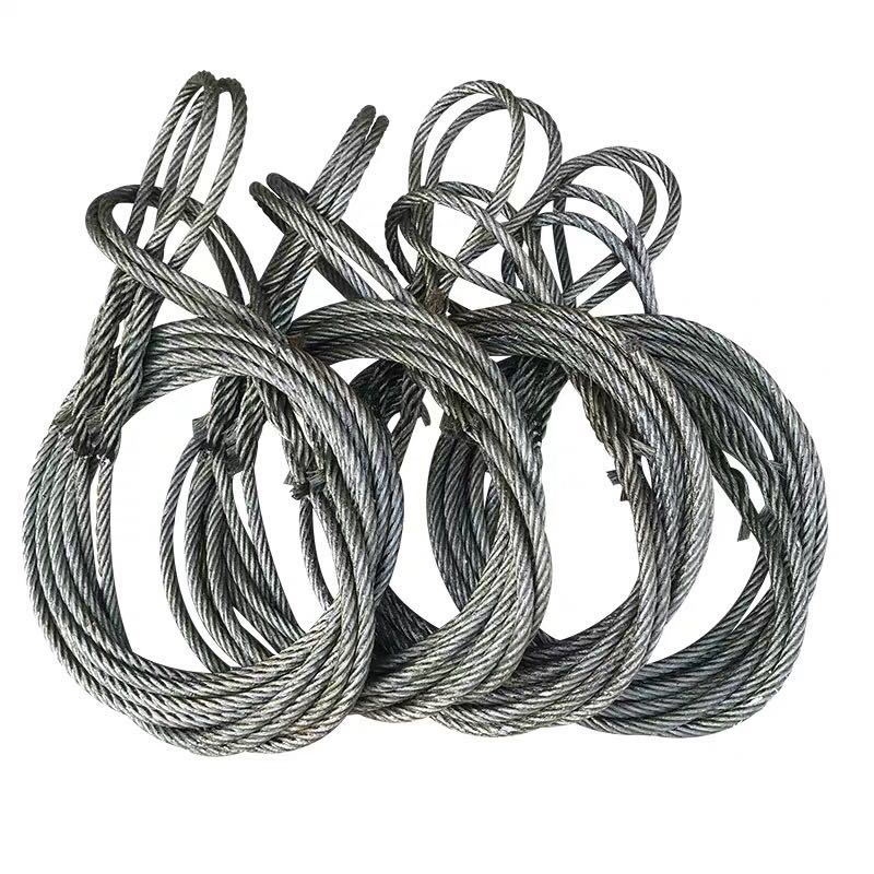
Cast steel wire rope slings are among the most reliable load-bearing assemblies in heavy industrial, construction, and offshore lifting operations. Engineered to handle extreme tension, they combine high-tensile wire rope bodies with precision-cast steel end fittings to deliver consistent, verifiable working load limits. Yet despite their robust design, premature failure remains a persistent and costly risk on active job sites.
Failure rarely occurs without warning. Most incidents trace back to a combination of mechanical misuse, inadequate inspection routines, and environmental degradation — all of which are preventable with the right knowledge and protocols. For procurement managers sourcing rigging hardware, rigging engineers specifying lift configurations, and site safety officers conducting compliance audits, understanding why these slings fail is as important as knowing how they are rated.
This article examines the root causes of cast steel wire rope sling failure under heavy loads, presents a structured failure mode reference table, and delivers actionable inspection and procurement guidance aligned with ASME B30.9 and EN 13414-1 standards. The goal: reduce unplanned downtime, mitigate liability exposure, and extend sling service life across your operations.
1. Understanding How Cast Steel Wire Rope Slings Are Constructed and Rated
1.1 Core Construction and Material Properties
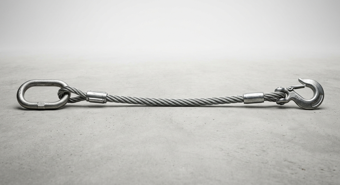
A cast steel wire rope sling consists of two primary components: the wire rope body and the cast steel end fittings. The rope body is typically configured in standard strand constructions such as 6×19 or 6×37, where individual high-carbon steel wires are helically wound around a fiber or independent wire rope core (IWRC). The IWRC configuration is preferred for heavy-load applications because it resists crushing under radial pressure and maintains rope geometry under tension.
The end fittings — hooks, master links, shackles, or ferrule-secured eyes — are manufactured from cast or forged steel grades with defined yield strength and impact toughness. Quality fittings are produced from alloy steel grades such as Grade 80 or Grade 100, heat-treated to achieve the hardness and ductility balance necessary to absorb dynamic loads without brittle fracture. The interface between the rope termination and the fitting is a critical stress concentration zone; improper swaging, casting defects, or material inconsistency at this junction are frequent precursors to failure.
Working load limit (WLL) is calculated by dividing the minimum breaking force (MBF) of the assembly by a defined design factor — typically 5:1 for standard wire rope slings per ASME B30.9. This means a sling rated at 10 tonnes WLL must withstand a minimum breaking load of 50 tonnes under controlled test conditions.
1.2 Load Rating Standards and Compliance Benchmarks
Two primary standards govern the design, testing, and use of wire rope slings in global markets:
- ASME B30.9 (North America): Specifies WLL calculation methods, proof load requirements (typically 2× WLL), inspection intervals, and discard criteria.
- EN 13414-1 (Europe): Defines equivalent safety factors, marking requirements, and conformity assessment procedures for wire rope sling assemblies.
A critical distinction procurement teams must understand: proof load (the load applied during factory testing to verify structural integrity) is not the same as break load (the ultimate load at which the assembly fails). Purchasing slings tested only to proof load without documented break load data leaves a significant gap in safety verification. Always request full test certificates, including material traceability and third-party verification from accredited laboratories.
2. Primary Causes of Failure Under Heavy Loads
2.1 Mechanical and Structural Failure Modes
The most immediate cause of sling failure is overloading beyond the rated WLL. This occurs when operators fail to account for sling angle reduction — a physics-driven phenomenon where the effective load on each sling leg increases as the angle from vertical decreases. At a 60° sling angle, each leg carries approximately 115% of its share of the vertical load. At 30°, that figure exceeds 200%. Rigging teams that ignore angle efficiency factors routinely subject slings to loads far beyond rated capacity.
Shock loading compounds this risk. When a load is dropped and arrested suddenly, the dynamic force spike can reach 2–5× the static load within milliseconds. Cast steel fittings are particularly vulnerable because their crystalline microstructure, while strong under static tension, is susceptible to brittle fracture under rapid impact loading.
Additional mechanical failure modes include:
- Crushed or kinked wire strands caused by running slings over sharp edges without edge protectors, permanently deforming the wire geometry and reducing load-bearing cross-section.
- Core collapse in IWRC ropes subjected to excessive bending over small-diameter rigging hardware, violating the minimum D/d (sheave diameter to rope diameter) ratio.
- Improper termination — swaged or speltered fittings applied outside specified tolerances, creating stress risers at the rope-to-fitting interface.
2.2 Material Degradation and Environmental Factors
Long-term service introduces degradation mechanisms that are not always visible during routine checks. Corrosion fatigue is the most insidious: surface rust on wire strands reduces the effective load-bearing diameter and initiates micro-cracks that propagate under cyclic loading. In marine, chemical plant, or high-humidity environments, galvanized or stainless steel rope constructions are essential — standard ungalvanized slings can lose 30–40% of their fatigue life within months of exposure.
Abrasion wear at contact points — where slings bear against load edges, hooks, or other hardware — progressively reduces wire diameter. A 10% reduction in rope diameter corresponds to an approximate 20% reduction in breaking strength.
Heat exposure embrittlement is a less-discussed but critical risk. Exposure to temperatures above 150°C (300°F) begins to alter the metallurgical properties of both the wire rope and cast steel fittings, reducing ductility and increasing susceptibility to sudden fracture. Slings used near welding operations, furnaces, or steam lines must be rated for elevated temperature service.
Failure Mode Reference Table
| Failure Mode | Primary Contributing Factor | Detection Method | Risk Level | Recommended Action |
|---|---|---|---|---|
| Wire breakage (rope body) | Overloading/fatigue cycling | Visual wire count inspection | Critical | Replace immediately |
| End fitting crack | Shock loading/casting defect | Visual + Magnetic Particle (MPI) | Critical | Replace immediately |
| Core collapse | D/d ratio violation | Diameter measurement, visual | High | Replace immediately |
| Surface corrosion | Environmental exposure | Visual / wire probe inspection | High | Monitor / Replace if pitting present |
| Abrasion wear | Edge contact without protectors | Diameter caliper measurement | High | Replace if >10% diameter reduction |
| Kinking / birdcaging | Torsional overload/misuse | Visual deformation check | High | Replace immediately |
| Heat embrittlement | Thermal exposure >150°C | Discoloration + hardness test | Moderate–Critical | Recertify or replace |
| Loose ferrule/swage | Improper termination | Visual + pull-through test | Critical | Replace immediately |
3. Critical Inspection Tips to Prevent In-Service Failure
3.1 Pre-Use and Periodic Visual Inspection Protocols
Every cast steel wire rope sling should undergo a pre-use inspection before each lift and a formal periodic inspection at intervals defined by usage frequency and environmental severity. Key discard criteria per ASME B30.9 and EN 13414-1 include:
- Broken wires: Remove from service if 10 or more randomly distributed broken wires are found in any rope lay length, or 5 or more broken wires in one strand within one lay length.
- Diameter reduction: Discard if the rope body shows a reduction of 10% or more from nominal diameter due to wear, corrosion, or core failure.
- End fitting integrity: Any visible cracks, deformation, elongation of hook throats, or opening of master links beyond tolerance requires immediate removal.
- Kinks, birdcaging, or core protrusion: These indicate permanent structural damage — no re-use under any circumstance.
- Corrosion: Pitting corrosion on wire surfaces, or corrosion that cannot be removed to reveal sound metal beneath, is grounds for discard.
Inspectors should use adequate lighting, wire probes for internal strand examination, and calibrated calipers for diameter measurement. Never rely solely on visual color change as a corrosion indicator.
3.2 Documentation, Tagging, and Recertification Requirements
Effective sling management requires a documented asset trail from manufacture to retirement. Each sling assembly should carry a permanent identification tag referencing: WLL, sling type, leg length, angle rating, manufacturer, and serial number. Color-coded inspection tags — updated on a defined cycle (typically quarterly or annually depending on usage intensity) — provide site-level visibility into compliance status.
Formal periodic inspections must be conducted by a designated person with documented competency. Records should capture: inspection date, inspector identity, findings, and disposition (continue service / monitor / remove). For critical lifts or high-cycle applications, third-party recertification at 12-month intervals is best practice, including proof load retesting and full dimensional verification.
4. Selecting the Right Cast Steel Wire Rope Sling for Heavy-Load Applications
4.1 Matching Sling Configuration to Load Type and Rigging Geometry
Single-leg slings are appropriate for stable, well-defined load attachment points. Multi-leg assemblies (2-, 3-, or 4-leg) distribute load across multiple attachment points and provide load stability — but each leg’s effective WLL must be derated based on the included angle between legs. For angles exceeding 120°, multi-leg slings should not be used without engineering review.
The D/d ratio — the ratio of the bend diameter around a hook or fitting to the rope diameter — directly affects the sling’s load capacity. Cast steel fittings with tight radii impose severe bending stress on the rope at the termination point. Minimum D/d ratios of 20:1 are recommended for most 6-strand constructions; falling below this threshold accelerates fatigue at the bend.
4.2 Total Cost of Ownership vs. Upfront Procurement Cost
Selecting cast steel wire rope slings on price alone is a high-risk procurement strategy. A sling that fails mid-lift generates costs that dwarf any initial savings: equipment damage, load loss, regulatory investigation, potential litigation, and — most critically — personnel injury or fatality.
Key supplier qualification criteria should include: ISO 9001-certified manufacturing, full material traceability documentation, third-party break load test certificates, and compliance marking per applicable regional standards (ASME or EN). Slings from certified suppliers with documented quality systems typically demonstrate 20–40% longer service intervals, directly reducing replacement frequency and total lifecycle cost.
FAQ
1. What is the most common reason cast steel wire rope slings fail during heavy lifts? The most frequent cause is sling angle-induced overloading combined with shock loading. Operators underestimate how steeply load increases on each sling leg as the rigging angle decreases from vertical, and dynamic force spikes during load pickup or arrest can exceed static WLL by a factor of 2–5×.
2. How many broken wires in a wire rope sling require immediate removal from service? Per ASME B30.9, remove the sling if 10 or more randomly distributed broken wires appear in one rope lay length, or if 5 or more broken wires are concentrated in a single strand within one lay. Any broken wire at an end fitting termination also requires immediate removal regardless of count.
3. What certifications should I verify when sourcing cast steel wire rope slings from a supplier? Verify: ISO 9001 quality management certification, third-party break load and proof load test certificates with traceable serial numbers, compliance marking per ASME B30.9 or EN 13414-1, and material certificates for both wire rope and cast steel fittings. For critical applications, request factory audit reports or approved vendor list status from recognized inspection bodies.
Conclusion
Cast steel wire rope slings do not fail randomly — they fail predictably when mechanical limits are exceeded, inspection protocols are neglected, or material degradation goes undetected. Understanding the specific failure modes, from shock-load-induced fitting fracture to corrosion fatigue and D/d ratio violations, gives procurement and safety teams the diagnostic framework needed to prevent incidents before they occur.
Implementing structured pre-use inspections, maintaining rigorous documentation and tagging systems, and selecting slings from certified suppliers with full traceability are not administrative burdens — they are the operational foundation of safe heavy-load rigging. Applied consistently, these practices reduce unplanned downtime, extend asset service life, and protect both personnel and organizational liability across every lift.