

Abstract
This article provides B2B procurement professionals and rigging engineers with a definitive reference on wire rope sling load capacity. It covers how Working Load Limits (WLL) are established, how safety factors are applied per industry standards, how sling diameter correlates to rated capacity, and how sling angle critically reduces effective working load.
Wire rope slings are the backbone of industrial lifting operations across construction, offshore, mining, and heavy manufacturing sectors. Yet a significant proportion of rigging failures trace back to a single root cause: misspecification of load capacity. Procurement teams that rely on breaking strength figures, ignore sling angle penalties, or overlook configuration multipliers routinely expose operations to overload risk — and regulatory liability.
This guide delivers the technical framework to specify wire rope slings correctly. Whether you are sourcing single-leg slings for vertical lifts or multi-leg assemblies for complex load geometries, the principles of WLL ratings, safety factors, rope construction, and angle reduction apply universally. Buyers will leave with actionable criteria for procurement specifications, certification requirements, and inspection protocols.
1. What Determines Wire Rope Sling Load Capacity?
1.1 Working Load Limit (WLL) vs. Breaking Strength
The most critical distinction in wire rope sling procurement is the difference between Working Load Limit (WLL) and Minimum Breaking Force (MBF).
Minimum Breaking Force — also called Minimum Breaking Load (MBL) — is the tensile force at which a wire rope assembly is expected to fail under controlled laboratory testing. It represents the absolute structural ceiling of the rope, not a safe operational parameter.
Working Load Limit, by contrast, is the maximum load a sling is permitted to carry under normal service conditions. It is derived by dividing the MBF by the applicable safety factor. For most industrial wire rope slings, this produces a WLL substantially below the breaking threshold.
Why does this matter for procurement? Because supplier datasheets sometimes prominently display breaking strength figures — numbers that appear impressively high but are operationally irrelevant. Specifying a sling based on MBF without applying the correct safety factor creates a systematic overload condition that may not be visible until failure occurs.
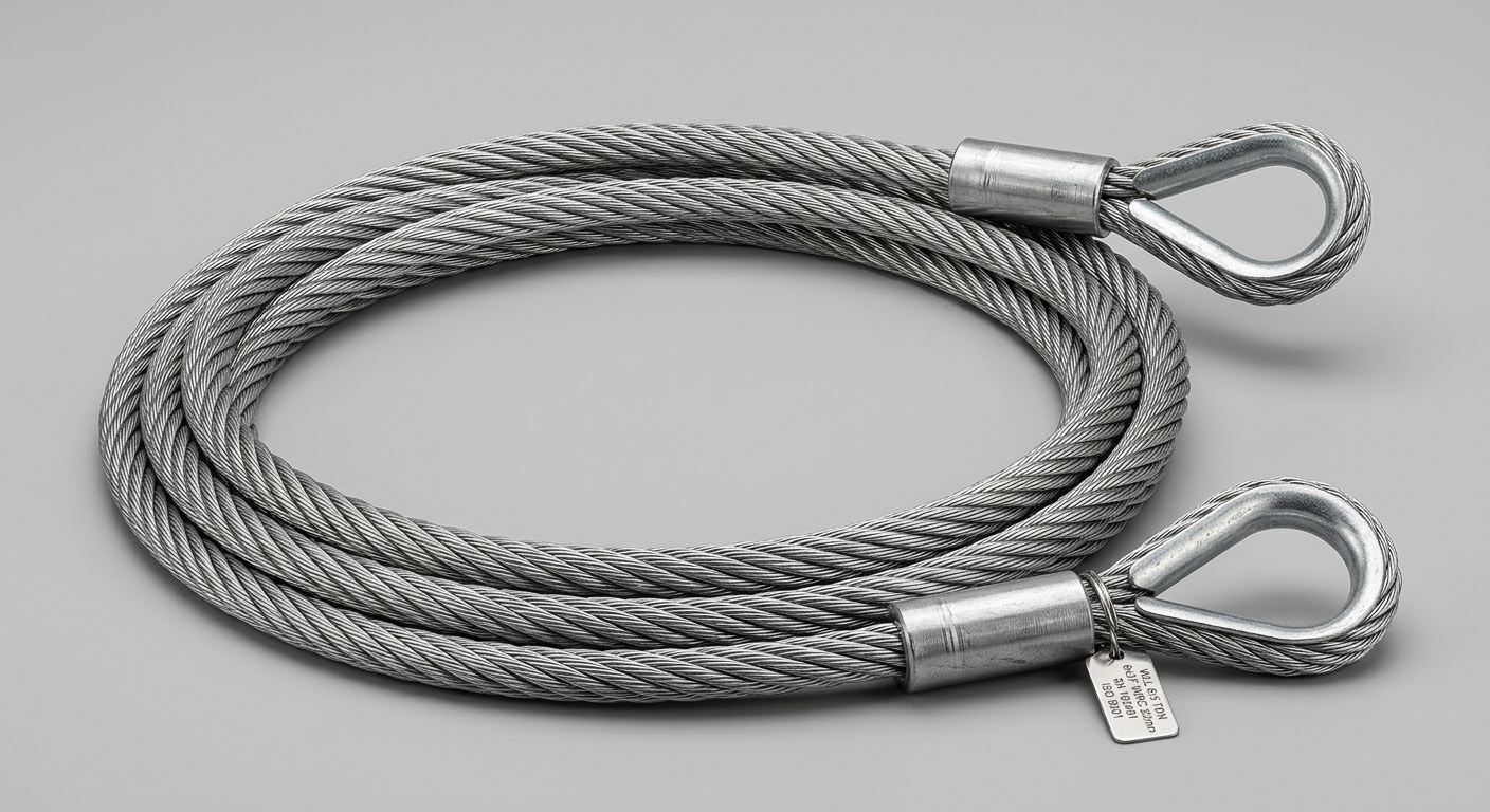
Procurement rule: All purchase orders, test certificates, and product markings must reference WLL — not breaking strength. Any supplier unable to provide WLL-rated documentation to ASME B30.9 or EN 13414 standards should be disqualified from the approved vendor list.
1.2 Safety Factor Standards for Wire Rope Slings
The industry-standard safety factor for wire rope slings is 5:1, meaning the MBF must be at least five times the rated WLL. This requirement is codified in:
- ASME B30.9 (North American standard for slings)
- EN 13414-1 (European standard for steel wire rope sling assemblies)
The calculation is straightforward:
WLL = MBF ÷ Safety Factor Example: A sling with an MBF of 50 tonnes carries a WLL of 10 tonnes (50 ÷ 5 = 10).
For critical or heavy-lift applications — offshore crane operations, nuclear facility lifts, or precision equipment installation — engineering teams may specify a higher safety factor (6:1 or 8:1) to account for dynamic loading, shock loads, or environmental degradation. This must be contractually specified at the procurement stage, as standard catalogue slings are rated at 5:1.
Regulatory compliance implications are significant. Under OSHA 29 CFR 1926.251 and equivalent EU Machinery Directive requirements, using a sling beyond its rated WLL constitutes a regulatory violation, regardless of whether failure occurs. Documented WLL ratings are not optional — they are a legal requirement in most industrial jurisdictions.
2. Wire Rope Sling Diameter & Construction vs. Load Capacity
2.1 How Rope Diameter and Core Type Affect WLL
Rope diameter is the primary determinant of base WLL. Load capacity scales with the cross-sectional steel area — a relationship that increases non-linearly with diameter. A 16 mm wire rope sling does not carry twice the load of an 8 mm sling; it carries approximately four times as much, reflecting the squared relationship between diameter and area.
Core type introduces a secondary but significant capacity variable:
- IWRC (Independent Wire Rope Core): A steel wire rope core that increases breaking strength by approximately 7.5% compared to fiber core equivalents of the same diameter. IWRC also provides superior crush resistance, making it the preferred specification for basket configurations and high-cycle industrial applications.
- Fiber Core (FC): Natural or synthetic fiber core offers greater flexibility and is suitable for lighter duty or irregular load shapes, but yields lower WLL ratings and reduced resistance to lateral compression.
Common constructions and their application profiles:
- 6×19 IWRC: High strength, moderate flexibility — suited to straight vertical lifts and general industrial rigging.
- 6×37 IWRC: Greater flexibility due to more wires per strand — preferred for complex rigging geometries and sheave-intensive applications.
- 8×19 IWRC: Enhanced flexibility with good fatigue resistance — used in marine and offshore applications where sling movement is frequent.
2.2 Sling Configuration and Its Multiplier Effect
Sling configuration directly multiplies or reduces the effective WLL relative to the single-leg baseline. Understanding these multipliers is essential for multi-leg assembly specification.
| Rope Diameter | Construction | Single-Leg WLL (t) | Vertical Basket WLL (t) | Choker WLL (t) | Standard |
|---|---|---|---|---|---|
| 10 mm / 3/8″ | 6×19 IWRC | 1.12 | 2.24 | 0.85 | ASME B30.9 |
| 13 mm / 1/2″ | 6×19 IWRC | 2.00 | 4.00 | 1.52 | ASME B30.9 |
| 16 mm / 5/8″ | 6×19 IWRC | 3.20 | 6.40 | 2.43 | ASME B30.9 |
| 19 mm / 3/4″ | 6×37 IWRC | 4.40 | 8.80 | 3.34 | EN 13414-1 |
| 22 mm / 7/8″ | 6×37 IWRC | 5.90 | 11.80 | 4.48 | EN 13414-1 |
| 25 mm / 1″ | 6×37 IWRC | 7.70 | 15.40 | 5.85 | EN 13414-1 |
Note: Values are representative. Always verify against manufacturer’s certified load tables for the specific sling assembly.
Configuration multipliers (relative to single-leg WLL at vertical):
- Vertical basket: 2.0× — both legs share load equally in a straight pull
- Choker: 0.75× — the choke angle creates a stress concentration that reduces rated capacity
- Two-leg bridle at 90°: 1.41× per leg — governed by sling angle (see Section 3)
3. How Sling Angle Affects Working Load Limit
3.1 The Sling Angle Factor Explained
Sling angle — measured from the horizontal plane to the sling leg — is one of the most underestimated variables in rigging load planning. As the angle decreases from vertical (90°), the tension in each sling leg increases dramatically to maintain vertical equilibrium, effectively reducing the usable WLL of the assembly.
The angle factor (AF) is calculated as:
AF = sin(θ) Where θ = angle of sling leg from horizontal
The effective WLL per leg in a multi-leg assembly equals:
Effective WLL = Single-Leg WLL × sin(θ)
At 90° (vertical), sin(90°) = 1.0 — no capacity reduction. At 30°, sin(30°) = 0.5 — each leg now carries twice the tension for the same vertical load, halving the effective WLL. This is why most standards, including ASME B30.9 and EN 13414, prohibit sling angles below 30° from horizontal in standard rigging practice. Below this threshold, tension escalation becomes extreme and sling failure risk increases sharply.
3.2 Practical Angle Reduction Examples for Rigging Planning
The following table illustrates the cumulative impact of sling angle on a two-leg bridle assembly using slings with a 5-tonne single-leg WLL:
| Sling Angle (from horizontal) | Angle Factor (sin θ) | Tension per Leg | Effective Assembly WLL |
|---|---|---|---|
| 90° (vertical) | 1.000 | 5.00 t | 10.00 t |
| 60° | 0.866 | 5.00 t | 8.66 t |
| 45° | 0.707 | 5.00 t | 7.07 t |
| 30° | 0.500 | 5.00 t | 5.00 t |
| Below 30° | < 0.500 | Exceeds WLL | Prohibited |
For rigging planners, this data carries a direct operational implication: a two-leg bridle assembly that appears to have a 10-tonne combined capacity at 90° delivers only 5 tonnes of effective lift at 30°. Rigging layouts must always be designed to maintain the highest practical sling angle. Where load geometry forces shallow angles, a longer sling or spreader beam should be specified to restore the angle above 45°.
4. Compliance Standards & Procurement Specifications
4.1 Key International Standards Governing WLL Ratings
Three primary standards govern wire rope sling WLL ratings in global industrial procurement:
- ASME B30.9: The dominant North American standard. Covers sling fabrication, WLL determination, marking requirements, and inspection criteria. Mandatory reference for US and Canadian industrial lifting operations.
- EN 13414-1: European standard for steel wire rope sling assemblies. Governs design factor (minimum 5:1), proof load testing, and CE marking requirements under the EU Machinery Directive.
- ISO 2408: International standard for steel wire ropes for general purposes — provides the rope construction and breaking force data that underpins sling WLL calculations globally.
Certification requirements for procurement:
- Test certificates referencing MBF and calculated WLL
- Conformity declaration (CE marking for EU supply chains)
- Sling tag or permanent marking showing: WLL, sling length, construction, and manufacturer identification
- Batch traceability to material test records
Buyers sourcing from international suppliers should explicitly require EN 13414-1 or ASME B30.9 compliance in RFQ documentation — not merely “ISO compliance,” which does not independently certify WLL ratings.
4.2 Inspection, Retirement Criteria & Load Capacity Integrity
A wire rope sling’s rated WLL applies only when the sling is in serviceable condition. Physical degradation directly compromises load capacity integrity, and continued use of a damaged sling at its original WLL constitutes an overload condition.
OSHA 29 CFR 1926.251 and EN 13414-3 mandate retirement or immediate removal from service when:
- Ten or more randomly distributed broken wires are found in one rope lay, or five or more broken wires in one strand within one rope lay
- Kinking, crushing, bird-caging, or core protrusion is visible
- Corrosion has caused pitting or significant cross-section reduction
- End fittings show cracks, deformation, or evidence of slippage
- Sling diameter has reduced by more than 1/3 of the nominal diameter
Inspection intervals: Pre-use visual inspection is mandatory before every lift. Documented periodic inspections — typically quarterly for high-cycle applications — must be maintained in a sling register with inspector identification, date, and findings.
For industrial buyers, maintaining documented inspection records is not only a safety requirement but a liability management tool. In the event of a lifting incident, absence of inspection records creates significant legal exposure.
FAQ
Q1: What is the standard safety factor for wire rope slings, and can it be customized for heavy-lift applications?
The standard safety factor is 5:1 per ASME B30.9 and EN 13414-1. For heavy-lift, offshore, or critical applications, engineering specifications may require 6:1 or 8:1 safety factors. This must be explicitly stated in procurement documents, as catalogue slings are rated at 5:1 by default. Suppliers should provide test certificates confirming the MBF against which the elevated safety factor was applied.
Q2: How do I calculate the actual WLL of a two-leg bridle sling at a 45° sling angle?
Multiply the single-leg WLL by the angle factor for 45° (sin 45° = 0.707), then multiply by the number of legs:
Assembly WLL = Single-Leg WLL × 0.707 × 2 legs
For a sling with a 5-tonne single-leg WLL: 5 × 0.707 × 2 = 7.07 tonnes effective WLL. Always use the horizontal angle measurement, not the angle from vertical.
Q3: What wire rope sling diameter and construction should I specify for a 10-tonne vertical lift?
For a straight vertical single-leg lift, specify a minimum 22 mm (7/8″) 6×37 IWRC sling with a rated single-leg WLL of ≥10 tonnes per EN 13414-1 or ASME B30.9. If using a vertical basket configuration, a 16 mm (5/8″) sling with a basket WLL of ≥10 tonnes may be acceptable. Always confirm against the manufacturer’s certified load table and account for any dynamic load factors in the application.
Conclusion
Selecting the correct wire rope sling load capacity is a multi-variable engineering decision, not a catalogue lookup. Procurement teams must anchor specifications to WLL — not breaking strength, apply the correct 5:1 safety factor per ASME B30.9 or EN 13414-1, and select rope diameter and construction based on verified load tables for the intended configuration.
Critically, sling angle must be calculated for every multi-leg assembly. A rigging plan that ignores angle reduction can silently reduce effective WLL by 50% or more — converting a compliant lift into an overload condition without changing a single piece of hardware.
Buyers who build these variables into procurement specifications, require certified test documentation, and enforce structured inspection protocols will achieve both regulatory compliance and measurable reduction in lifting-related operational risk. For complex applications, engaging a certified rigging engineer to validate sling selection against actual load geometry remains the highest-value investment in lifting safety.