

Abstract
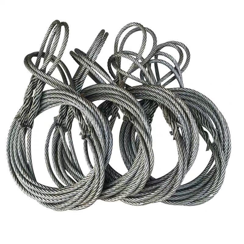
Wire rope slings are critical load-bearing components across construction, offshore, mining, and heavy manufacturing operations. Yet one of the most frequently misunderstood aspects of their use is how safe lifting capacity is actually determined. The answer is not a single stamped number — it is a compound value shaped by rated working load limit, hitch configuration, sling angle, and the physical condition of the sling itself.
This article provides a technically grounded breakdown of how WLL is derived from wire rope construction, how angle and hitch type modify that rated capacity in real-world lifts, and what degradation factors reduce capacity over time. It also outlines the compliance standards and procurement documentation that B2B buyers, rigging engineers, and safety managers must verify before sourcing. Whether you are specifying slings for a new project or reviewing your current inventory against regulatory requirements, this guide delivers the precision you need to make informed, defensible purchasing decisions.
1. What Is the Working Load Limit (WLL) of a Wire Rope Sling?
1.1 How WLL Is Calculated
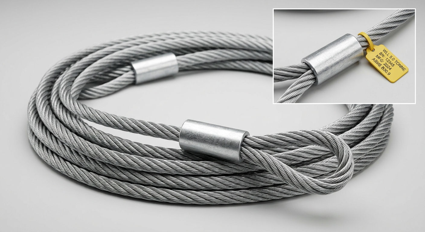
The Working Load Limit of a wire rope sling is the maximum mass or force that the sling is rated to exert in a straight vertical pull under normal service conditions. It is derived directly from the sling’s Minimum Breaking Load (MBL) — also called Minimum Breaking Force (MBF) — divided by a prescribed safety factor.
Under ASME B30.9 and most international standards, the standard design factor for wire rope slings is 5:1. This means a sling with an MBL of 50 tonnes carries a vertical WLL of 10 tonnes. The MBL itself is determined by the wire rope’s construction parameters:
- Rope diameter: Larger diameters yield higher aggregate wire cross-sections and therefore higher breaking loads.
- Strand and wire count: Common constructions include 6×19 (stiffer, abrasion-resistant, suited for general lifting) and 6×37 (more flexible, preferred for complex reeving or tight sheave systems).
- Kerntype: Independent Wire Rope Core (IWRC) provides approximately 7.5% greater breaking strength than a Fiber Core (FC) equivalent and offers superior crush resistance — a decisive factor in heavy industrial applications.
Manufacturers calculate WLL using standardized load tables cross-referenced against these construction variables, with values verified through proof load testing before the sling leaves the factory.
1.2 WLL vs. Breaking Strength: What Buyers Must Distinguish
A persistent and potentially dangerous misconception in procurement is treating Minimum Breaking Load as an operational limit. MBL is a laboratory-tested destruction threshold, not a service rating. Operating a sling at or near its MBL eliminates the safety margin engineered to absorb dynamic shock loads, load eccentricity, and in-service degradation.
For procurement teams, this distinction has direct compliance and liability implications. Purchase orders should always specify WLL — not MBL — as the governing capacity parameter. Suppliers must provide documentation that clearly separates these values. Any sling tag or test certificate that only lists breaking strength without a stated WLL should be treated as non-conforming to ASME B30.9 and EN 13414-1 requirements.
📊 Wire Rope Sling WLL Reference Chart
| Rope Diameter | Construction | Core Type | Vertical WLL (t) | Choker WLL (t) | Basket WLL (t) |
|---|---|---|---|---|---|
| 10 mm | 6×19 | FC | 0.85 | 0.64 | 1.70 |
| 13 mm | 6×19 | IWRC | 1.50 | 1.13 | 3.00 |
| 16 mm | 6×37 | IWRC | 2.24 | 1.68 | 4.48 |
| 20 mm | 6×37 | IWRC | 3.55 | 2.66 | 7.10 |
| 25 mm | 6×37 | IWRC | 5.50 | 4.13 | 11.00 |
| 32 mm | 6×37 | IWRC | 9.00 | 6.75 | 18.00 |
Reference values based on ASME B30.9 and EN 13414-1 rated single-leg assemblies. Always verify against manufacturer-certified load tables for the specific sling supplied.
2. How Sling Angle and Hitch Type Affect Lifting Capacity
2.1 The Sling Angle Factor: Why Angle Reduces WLL
When a sling is rigged at an angle rather than vertically, the tension in each leg increases to maintain equilibrium with the vertical load. This tension increase is quantified by the angle efficiency factor, which reduces the effective WLL proportionally.
| Sling Angle (from horizontal) | Angle Factor | Effective WLL (% of rated) |
|---|---|---|
| 90° (vertical) | 1.000 | 100% |
| 60° | 0.866 | 86.6% |
| 45° | 0.707 | 70.7% |
| 30° | 0.500 | 50.0% |
At 30°, each sling leg carries twice the tension it would in a vertical configuration — effectively halving the usable WLL. ASME B30.9 recommends a minimum sling angle of 30° from horizontal; angles below this threshold generate tension loads that can exceed rated capacity even under moderate payloads. Rigging engineers should design lift plans to maintain angles of 60° or greater wherever load geometry permits.
2.2 Hitch Configurations and Their Capacity Multipliers
The three standard hitch types produce fundamentally different load distributions:
- Vertical hitch (straight lift): Load is applied directly to a single sling leg. Effective capacity = 1× WLL. Suitable for symmetrical loads with a defined lift point.
- Choker hitch: The sling wraps around the load and chokes back on itself. The contact angle reduces effective capacity to approximately 0.75× WLL (75%). Provides load control and is preferred for cylindrical or bundled items, but is the most capacity-restrictive configuration.
- Basket hitch: Both ends of the sling connect to the hook while the load rests in the bight. When the load is centered and the sling legs are vertical, basket hitch doubles the effective capacity to 2× WLL. However, this multiplier decreases as the leg angle departs from vertical — the angle efficiency factor must still be applied.
For multi-leg assemblies (2-leg, 3-leg, 4-leg), rated WLL values are provided in manufacturer load tables at specified angles. A 2-leg bridle at 60° does not simply double the single-leg WLL; the angle factor is already incorporated into the assembly rating.
3. Key Factors That Influence Real-World Wire Rope Sling Capacity
3.1 Physical & Construction Variables
Beyond diameter and strand count, several construction decisions directly impact the load capacity and service life of a wire rope sling:
- Core construction: IWRC slings outperform FC slings in crushing resistance and maintain rounder cross-sections under load, preserving rated capacity across more lift cycles.
- Lay type: Regular lay (wires and strands twisted in opposite directions) offers better abrasion resistance. Lang’s lay provides greater fatigue resistance but requires more careful handling to prevent kinking.
- Number of legs: Multi-leg assemblies distribute load across multiple lines. A 4-leg sling assembly does not provide 4× the single-leg WLL — rated capacity tables account for load distribution assumptions, typically crediting only 3 legs as actively loaded at any given time due to load geometry variability.
- End fittings: Ferrule-secured eyes, mechanical splice eyes, swaged sockets, and spelter sockets each carry different efficiency ratings. Ferrule-secured and swaged terminations typically achieve 95–100% of rope breaking strength; hand-spliced eyes may be rated lower depending on construction.
3.2 Environmental & Operational Degradation Factors
A sling’s rated WLL assumes a new, undamaged assembly. In-service conditions systematically reduce this capacity:
- Corrosion: Surface rust reduces cross-sectional wire area. Internal corrosion — particularly in FC-core slings — is not visible during external inspection and can cause sudden failure.
- Fatigue cycles: Repeated bending over sheaves or hooks accumulates wire fatigue. The D/d ratio (sheave or hook diameter to rope diameter) is critical; ratios below 20:1 accelerate fatigue degradation significantly.
- Temperature: Wire rope slings lose strength at sustained temperatures above 120°C. High-temperature applications require slings with appropriate ratings and specialist lubrication.
- Inspection triggers per ASME B30.9 / ISO 4309: Remove from service when any of the following are observed — broken wires exceeding threshold counts per lay length, visible kinking or birdcaging, severe corrosion, damaged end fittings, or illegible identification tags.
4. Compliance Standards and Procurement Verification
4.1 Applicable Standards Buyers Must Reference
Three primary standards govern wire rope sling design, manufacture, and use in most global markets:
- ASME B30.9 (North America): Covers sling types, WLL tables, marking requirements, inspection intervals, and removal-from-service criteria.
- EN 13414-1 (Europe): Specifies safety requirements for steel wire rope slings, including design factor, proof load testing, and CE marking obligations.
- ISO 2766 / ISO 4309: Addresses wire rope inspection methodology and discard criteria applicable across international jurisdictions.
Every sling supplied for industrial use must carry a permanent identification tag stating: WLL, rope diameter and construction, sling length, number of legs, and the manufacturer’s unique serial or batch number. Test certificates must be traceable to this identification. Buyers sourcing from international suppliers should require third-party inspection reports and material mill certificates as part of standard documentation packages.
4.2 How to Specify Wire Rope Slings in a Purchase Order
A technically complete RFQ for wire rope slings should specify:
- WLL at the required hitch configuration and sling angle
- Rope diameter and construction (e.g., 6×37 IWRC)
- Number of legs and assembly configuration
- Sling length (eye-to-eye or overall)
- End fittings: type (hook, shackle, ferrule eye, swaged socket), grade, and material
- Surface finish: galvanized, stainless, or ungalvanized for specific environmental conditions
- Applicable standard: ASME B30.9 or EN 13414-1
- Traceability documentation: test certificate, proof load confirmation, identification tag format
Omitting any of these parameters risks receiving non-conforming product that cannot be legally or safely deployed on a regulated lift site.
Veelgestelde vragen
1. What is the standard safety factor for wire rope slings, and can it be adjusted for critical lifts?
The standard design factor under ASME B30.9 and EN 13414-1 is 5:1 (MBL to WLL). For engineered critical lifts — defined as lifts where failure would result in significant personnel risk or asset damage — lift plans may specify additional derating, effectively applying a higher operational safety factor. This is a project engineering decision documented in the lift plan, not a modification to the sling’s rated WLL.
2. How does a 4-leg wire rope sling affect the working load limit compared to a 2-leg sling?
A 4-leg assembly does not provide double the WLL of a 2-leg assembly. Standard load tables for 4-leg slings credit 3 legs as the effective load-bearing count, accounting for the statistical likelihood that load geometry prevents perfectly equal distribution across all four legs simultaneously. Always use the manufacturer’s rated assembly WLL at the specified angle rather than calculating from single-leg values.
3. What inspection criteria determine when a wire rope sling must be removed from service?
Per ASME B30.9, mandatory removal criteria include: broken wires exceeding the standard threshold per rope lay length, evidence of kinking, birdcaging, or crushing, corrosion that pits or reduces wire diameter, heat damage, damaged or missing end fittings, and any illegible or missing identification tags. Inspection frequency should be proportional to service intensity — daily pre-use checks are required; periodic formal inspections must be documented.
Conclusie
A wire rope sling’s safe lifting capacity is never a single fixed number. It is the product of rated WLL derived from rope construction and safety factor, modified by hitch configuration, further reduced by sling angle, and continuously affected by in-service degradation. Procurement teams and rigging engineers must evaluate all four dimensions together — not in isolation — to ensure both operational safety and regulatory conformance.
Specifying wire rope slings correctly at the purchase order stage, verifying compliance documentation, and maintaining a disciplined inspection program are not administrative formalities. They are the technical foundation on which every safe lift is built.