

Abstract
Determining how much weight a D shackle can safely hold is not as straightforward as reading a single number stamped on the body. Safe lifting capacity is a function of multiple interacting variables: the shackle’s Working Load Limit (WLL), its physical dimensions, the direction and nature of the applied load, the material grade, and its compliance with recognized international standards.
This article provides a structured technical reference for procurement engineers, rigging supervisors, and safety managers who need to make defensible, standards-compliant shackle selections. It covers how WLL is defined and calculated, how shackle size and pin diameter correlate to rated capacity, how angular loading and environmental factors derate safe capacity, and what certifications to require before deploying D shackles in critical lifting operations. Whether you are specifying hardware for offshore crane lifts, construction hoisting, or marine towing, understanding the full capacity framework—not just the stamped rating—is essential for operational safety and regulatory compliance.
1: Understanding Working Load Limit (WLL) in D Shackles
1.1: How WLL Is Defined and Calculated
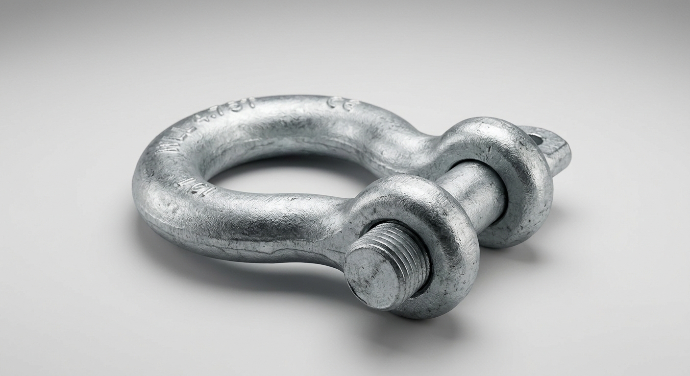
The Working Load Limit (WLL) is the maximum load a D shackle is designed to sustain in a specific configuration during regular service. It is not the load at which the shackle will fail—it is the ceiling below which the shackle must always operate.
WLL is derived from the Minimum Breaking Load (MBL) by applying a design safety factor. For most industrial D shackles, the safety factor is 4:1, meaning a shackle with a 5-tonne WLL has a minimum breaking load of at least 20 tonnes. In higher-risk applications—such as personnel lifting or offshore critical picks—a 6:1 safety factor is commonly mandated by regulatory bodies.
This distinction is operationally critical. Engineers must never treat MBL as a usable load threshold. The safety factor exists to absorb dynamic shock loads, load path uncertainties, material fatigue, and environmental degradation over the shackle’s service life. Using WLL as the operational ceiling preserves this margin.
WLL is also configuration-specific. A shackle rated at 4.75 tonnes achieves that rating only when the load is applied in-line along the plane of the bow, with the pin fully secured. Any deviation from this configuration reduces effective capacity, as addressed in Section 2.
1.2: How Shackle Size and Pin Diameter Affect WLL
Body diameter and pin diameter are the primary dimensional drivers of WLL. As shackle size increases, both the cross-sectional area resisting tensile stress and the pin’s shear capacity increase, producing a predictable progression in rated capacity.
The following reference table illustrates standard size-to-WLL relationships for forged alloy steel D shackles:
| Shackle Size | Pin Diameter | WLL (tonnes) | Min. Breaking Load (tonnes) | Standard Reference |
|---|---|---|---|---|
| 1/4″ (6 mm) | 6 mm | 0.5 | 2.0 | EN 13889 / ASME B30.26 |
| 3/8″ (10 mm) | 10 mm | 1.0 | 4.0 | EN 13889 / ASME B30.26 |
| 1/2″ (13 mm) | 13 mm | 2.0 | 8.0 | EN 13889 / ASME B30.26 |
| 5/8″ (16 mm) | 16 mm | 3.25 | 13.0 | EN 13889 / ASME B30.26 |
| 3/4″ (19 mm) | 19 mm | 4.75 | 19.0 | EN 13889 / ASME B30.26 |
| 1″ (25 mm) | 25 mm | 8.5 | 34.0 | EN 13889 / ASME B30.26 |
| 1-1/4″ (32 mm) | 32 mm | 13.5 | 54.0 | EN 13889 / ASME B30.26 |
| 1-1/2″ (38 mm) | 38 mm | 17.0 | 68.0 | EN 13889 / ASME B30.26 |
Note: Values are indicative for Grade 6 alloy steel shackles. Always verify against manufacturer’s certified documentation.
Selecting a shackle based on body size alone without confirming material grade and certification can result in significant capacity overestimation, particularly when comparing carbon steel and alloy steel products of identical dimensions.
2: Key Factors That Affect Safe Lifting Capacity
2.1: Load Direction and Angular Loading Derating
A D shackle achieves its full rated WLL only when the load acts axially through the center plane of the bow—that is, when the resultant force is perfectly aligned with the shackle’s longitudinal axis. In practice, rigging geometries frequently introduce angular deviation, and this has a direct, measurable impact on safe capacity.
Angular loading occurs when sling legs converge at an angle rather than hanging vertically. As the included angle between sling legs increases, the tension in each leg—and therefore the force transmitted through the shackle—increases substantially:
| Sling Angle (from vertical) | Load Multiplier on Shackle | Effective WLL Reduction |
|---|---|---|
| 0° (vertical) | 1.00× | None |
| 30° | 1.04× | ~4% |
| 45° | 1.41× | ~29% |
| 60° | 2.00× | ~50% |
| 90° | Exceeds safe use | Not recommended |
At 60° from vertical (a 120° included angle between sling legs), the load on each shackle effectively doubles. A 4.75-tonne WLL shackle used in a 60° two-leg bridle can only safely support 2.375 tonnes of actual lifted load per leg. Rigging engineers must calculate the tension per leg and ensure it does not exceed the shackle’s WLL—not the total load.
Side loading—where the force acts laterally across the bow rather than along its axis—is particularly damaging. Most manufacturers derate D shackles to 25–33% of WLL under side-loading conditions. D shackles should never be used as the primary connection point in applications where side loading is unavoidable; bow (anchor) shackles are more appropriate in those configurations.
2.2: Material Grade, Surface Condition, and Environmental Factors
Material grade is the single most important determinant of WLL for a given shackle size. Two shackles of identical dimensions can have dramatically different ratings depending on whether they are manufactured from carbon steel or alloy steel:
- Carbon steel shackles (Grade 4): Lower tensile strength, lower WLL per unit size, typically used in non-critical or light-duty applications.
- Alloy steel shackles (Grade 6 or Grade 8): Higher tensile and yield strength, capable of significantly greater WLL in the same physical envelope. Grade 8 alloy shackles are standard for offshore and heavy industrial use.
Beyond base material, several service conditions reduce effective capacity:
- Corrosion and pitting: Surface corrosion reduces the effective cross-section and introduces stress concentration points. Shackles showing visible pitting, rust penetration, or more than 10% dimensional reduction should be removed from service immediately.
- Shock loading: Dynamic or impact loads can momentarily exceed the static WLL by a factor of 2× or more. Rigging systems subject to shock loading require additional derating—typically 50% of static WLL as a working ceiling.
- Elevated temperatures: Alloy steel shackles lose tensile strength above 200°C. Operations in high-temperature environments must reference manufacturer-specific derating curves.
- Chemical exposure: Acids, strong alkalis, and hydrogen sulfide environments can cause stress corrosion cracking in alloy steel. Stainless steel or specialty-coated shackles may be required in these conditions.
3: Compliance Standards and Certification Requirements
3.1: Major International Standards for D Shackles
Three primary standards govern D shackle design, testing, and marking for industrial applications:
- ASME B30.26 (USA): Covers rigging hardware including shackles. Specifies design factors, proof load testing at 2× WLL, and mandatory marking requirements including manufacturer identification, WLL, and grade.
- EN 13889 (Europe): The European harmonized standard for forged steel shackles. Requires proof load testing, traceability to heat number, and CE marking for shackles used within the EU. Specifies Grade 4, 6, and 8 classifications.
- AS 3765 (Australia/New Zealand): Closely aligned with EN 13889. Mandatory for lifting equipment used in Australian workplaces under WHS regulations.
All three standards require proof load testing at a multiple of WLL (typically 2× for EN 13889) before a shackle enters service. Shackles must carry permanent embossed or stamped markings—not paint or adhesive labels—indicating WLL, manufacturer code, and material grade.
3.2: How to Verify a Shackle’s Rated Capacity Before Use
Before deploying any D shackle in a lifting operation, verification should follow a structured protocol:
- Read the embossed markings: Confirm WLL, grade, and manufacturer code are permanently marked on the shackle body. Absent or illegible markings are grounds for immediate rejection.
- Request the material test certificate (MTC): Certified shackles should be traceable to a mill heat number and accompanied by a third-party test report confirming proof load and dimensional compliance.
- Cross-reference with manufacturer documentation: Verify that the marked WLL matches the published capacity chart for that size and grade.
- Inspect for counterfeits: Counterfeit rigging hardware is a documented problem in global supply chains. Red flags include unusually low pricing, non-standard markings, inconsistent surface finish, and absence of traceable certification. Purchase only from authorized distributors with verifiable supply chain documentation.
4: Selecting the Right D Shackle for Your Application
4.1: Matching Shackle WLL to Rigging System Requirements
Shackle selection must be integrated into the broader rigging system calculation, not treated as an isolated component decision. The process follows a defined sequence:
- Determine the total rigging load: Include the weight of the lifted object plus dynamic load factors (typically 1.3× for standard crane lifts, higher for offshore or shock-loaded applications).
- Calculate load per attachment point: For multi-leg rigging, account for sling angles to determine tension per leg (see Section 2.1).
- Select shackle WLL ≥ calculated load per attachment point: Do not select the minimum-rated shackle that technically meets the load. Apply a practical margin, particularly for repeated-use hardware.
- Verify the weakest link: The shackle’s WLL must be compatible with the WLL of every connected component—slings, hooks, master links, and lifting points. The system is only as strong as its lowest-rated element.
4.2: Common Industrial Use Cases and Capacity Requirements
| Application | Typical Load Range | Recommended Shackle Grade | Key Requirement |
|---|---|---|---|
| Construction hoisting | 1–25 tonnes | Grade 6 alloy steel | ASME B30.26 / EN 13889 certification |
| Offshore lifting | 5–500+ tonnes | Grade 8 alloy steel | DNV-GL or Lloyd’s Register approval |
| Marine and towing | 2–50 tonnes | Grade 6/8, galvanized or SS | Corrosion resistance, MBL documentation |
| Utilities and telecom | 0.5–5 tonnes | Grade 6 alloy steel | Lightweight, high-cycle fatigue rating |
| Mining and heavy industry | 10–200 tonnes | Grade 8 alloy steel | Shock load derating, third-party cert |
Offshore lifting applications impose the most stringent requirements, often mandating third-party certification from classification societies such as DNV, Lloyd’s Register, or Bureau Veritas, in addition to standard EN 13889 compliance.
Veelgestelde vragen
Q1: What is the difference between a D shackle’s working load limit and its breaking strength?
The WLL is the maximum load permitted during normal service operations. The breaking strength (MBL) is the load at which the shackle will structurally fail. For standard industrial D shackles, the MBL is 4× the WLL—meaning a 5-tonne WLL shackle has an MBL of approximately 20 tonnes. This 4:1 safety factor must never be deliberately consumed; it exists to absorb unknowns in the load path, dynamic effects, and material degradation over time.
Q2: How does load angle reduce the safe lifting capacity of a D shackle?
As sling angles increase from vertical, the tension in each sling leg—and the corresponding force through the shackle—increases. At a 60° angle from vertical, the load on the shackle doubles relative to the actual lifted weight. Engineers must calculate per-leg tension based on rigging geometry and ensure it remains below the shackle’s WLL. Side loading, where force acts laterally across the bow, reduces effective capacity to as little as 25% of the rated WLL.
Q3: Which certifications should I require when purchasing D shackles for industrial lifting?
At minimum, require compliance with EN 13889 (Europe), ASME B30.26 (North America), or AS 3765 (Australia), depending on your jurisdiction. Request material test certificates traceable to a heat number and third-party proof load test reports. For offshore applications, require additional certification from an accredited classification society. Reject any hardware that cannot provide traceable documentation—embossed markings alone are insufficient for critical lifting operations.
Conclusie
Selecting a D shackle based solely on physical size is a technically insufficient and potentially hazardous approach to rigging system design. Safe lifting capacity is determined by the intersection of WLL rating, pin and body diameter, material grade, load direction, and environmental service conditions—all of which must be evaluated together.
Procurement teams and rigging engineers should establish a standardized selection workflow: calculate total and per-attachment-point loads including dynamic factors, apply angular loading derating where applicable, match shackle WLL to the weakest-link requirement of the complete rigging system, and verify compliance through traceable certification documentation. The size-to-WLL reference charts in this article provide a starting framework, but manufacturer-certified data sheets and third-party test reports remain the authoritative source for any critical lift.
A correctly specified, certified, and inspected D shackle is one of the most reliable components in an industrial rigging system. Compromising on any element of this selection process introduces risk that no safety factor can fully compensate for.