

Абстракт
Bow shackles are a cornerstone of rigging and lifting operations worldwide, yet side loading remains one of the most underreported and least-understood causes of in-service failure. Unlike overloading—which is relatively easy to identify and prevent—side loading often occurs incrementally, through misrigging, multi-leg sling geometry, or gradual load drift, without triggering any immediate visible warning.
The consequences are severe. A shackle operating at a load angle of just 45° from its intended axis can retain as little as 65–70% of its stamped Working Load Limit (WLL). At 90° side loading, that figure can drop below 50% in certain designs. Yet procurement specifications routinely list only the in-line WLL, leaving a significant liability gap between what buyers believe they are purchasing and what the hardware will actually sustain in field conditions.
This article examines the mechanical reasons bow shackles lose rated capacity under angular or side loads, identifies the design variables that determine resistance, and outlines the inspection and procurement criteria that site engineers and sourcing teams must verify before specifying a shackle for multi-leg or off-axis lifting applications. Understanding these failure mechanisms is not a theoretical exercise—it is a prerequisite for safe, compliant, and cost-effective rigging system design.
1. The Mechanics of Side Loading: Why Bow Shackles Are Vulnerable
1.1 How Load Angle Degrades Rated Capacity
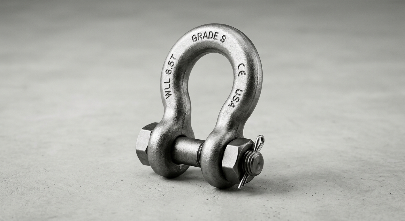
A bow shackle’s rated WLL is established under strictly in-line, axial loading conditions. When that load vector deviates from the shackle’s central axis, the stress distribution across the bow body changes fundamentally. Instead of pure tensile stress distributed symmetrically through the bow cross-section, the component now experiences a combination of bending moment, shear force, and torsional stress concentrated at the most vulnerable transition point: the bow-to-pin junction.
The bending stress at this junction increases non-linearly with load angle. Engineering data from shackle manufacturers and rigging standards consistently show the following approximate capacity retention curve:
| Load Angle from Vertical | Approximate WLL Retention |
|---|---|
| 0° (in-line) | 100% |
| 30° | ~85–90% |
| 45° | ~65–75% |
| 60° | ~50–60% |
| 90° (full side load) | ~35–50% |
These figures vary by design and material grade, but the directional trend is unambiguous: even moderate angular deviation imposes significant capacity loss. The pin-to-bow interface amplifies this effect because the pin acts as a fulcrum, concentrating bending stress at the inner bore of the bow ears rather than distributing it through the full cross-section.
1.2 Bow Geometry vs. Dee Shackle: Structural Trade-offs
The wider, rounded bow profile that makes bow shackles preferable for multi-leg sling assemblies—allowing multiple sling legs to seat without mutual interference—is precisely the geometry that increases lateral instability under off-axis tension. The extended bow arc creates a longer moment arm relative to the pin centerline. When a side load is applied, this moment arm translates directly into a higher bending moment at the bow ears.
By contrast, a dee shackle’s narrower, D-shaped body keeps the load path closer to the pin axis, offering better resistance to in-plane side loads. However, dee shackles cannot accommodate multi-leg slings effectively, which is why bow shackles dominate multi-point lifting applications—and why understanding their side load limitations is operationally critical. Specifying a bow shackle without accounting for actual load geometry is a design error, not a usage error.
2. Design Variables That Determine Side Load Resistance
2.1 Material Grade, Forging Method, and Body Proportions
Not all bow shackles are structurally equivalent, even when they carry identical WLL stamps. The three variables with the greatest influence on side load performance are material grade, manufacturing method, and bow body proportions.
Material Grade: Grade S (also referred to as Grade 6 in some European classifications) alloy steel is the minimum acceptable specification for industrial lifting bow shackles. Grade S alloy steel typically offers a tensile strength of 800–1000 MPa with controlled ductility, allowing the shackle to deform visibly before fracture under overload—a critical safety characteristic. Lower-grade carbon steel or ungraded hardware store shackles lack this ductility margin and are prone to sudden brittle fracture under side load stress concentration.
Forging Method: Drop-forged construction is mandatory for any shackle used in lifting. The forging process aligns the grain structure of the steel along the bow’s load path, maximizing tensile and fatigue strength. Cast shackles, which may appear visually identical, have random grain orientation and are significantly more susceptible to crack initiation at stress concentration points—precisely the locations where side loading applies its highest bending stress.
Body Proportions: A bow shackle with a higher width-to-thickness ratio at the bow ears provides greater resistance to out-of-plane bending. Buyers should request dimensional drawings and verify that bow ear thickness meets or exceeds the manufacturer’s grade specification minimums, not just the WLL stamping.
2.2 Pin Type, Collar Fit, and Securing Mechanism
The pin assembly is the second critical design variable. Two primary configurations exist: screw pin and safety bolt pin (also called bolt-nut-cotter pin).
Screw Pin Shackles are quick to deploy but are inappropriate for dynamic or long-duration lifts where vibration can cause the pin to back out. Under side loading, a partially backed-out screw pin reduces effective thread engagement, dramatically lowering the load at which the pin can be ejected from the bow.
Safety Bolt Pin Shackles use a bolt, nut, and cotter pin arrangement that prevents accidental disassembly. For applications involving side loading, angular sling geometry, or sustained dynamic loads, safety bolt pins are the correct specification. The cotter pin mechanically locks the nut against rotation, maintaining full thread engagement regardless of vibration or lateral force.
Collar Fit Tolerance: Pin-to-bore clearance is equally important. Excessive clearance—sometimes called “pin slop”—allows the pin to shift laterally under side load, concentrating stress on one side of the bow ear bore rather than distributing it across the full bearing surface. Buyers should specify and verify that pin-to-bore clearance conforms to the manufacturer’s tolerance standard, typically within 0.1–0.3 mm for industrial-grade shackles.
| Parameter | Screw Pin Bow Shackle | Safety Bolt Bow Shackle |
|---|---|---|
| WLL Range (typical) | 0.5 – 55 tonnes | 0.5 – 150+ tonnes |
| Side Load Suitability | Limited | Preferred |
| Pin Retention Under Vibration | Low | High |
| Material Grade (minimum) | Grade S Alloy Steel | Grade S Alloy Steel |
| Standard Compliance | EN 13889 / ASME B30.26 | EN 13889 / ASME B30.26 |
| Recommended Application | Short-duration, in-line lifts | Multi-leg, angular, dynamic lifts |
3. Compliance Standards and Rating Limits Buyers Overlook
3.1 What EN 13889, ASME B30.26, and US Fed Spec RR-C-271 Actually State About Side Loading
Three primary standards govern forged steel shackles in global procurement: EN 13889 (European), ASME B30.26 (North American), and US Federal Specification RR-C-271. All three establish WLL under in-line axial loading conditions. Their treatment of side loading, however, differs in specificity.
EN 13889 requires that shackles be marked with the WLL for straight pull only and explicitly states that the manufacturer must provide derating guidance for angular loading. The standard does not mandate a universal derating table but requires this information to be available in the product documentation.
ASME B30.26 is more prescriptive: it states that shackles shall not be side loaded unless the manufacturer has specifically rated the product for such use and that “in-line load only” markings carry legal weight in liability determinations. Rigging configurations that impose side loads on an unrated shackle constitute a non-compliant application.
RR-C-271 focuses primarily on proof load requirements and material certification but does not address angular loading derating in detail—a gap that procurement teams relying solely on this specification must close through supplementary manufacturer documentation.
The practical implication: “in-line load only” is not a suggestion. It is a design boundary with direct liability consequences.
3.2 Proof Load vs. Working Load Limit: Misapplication in Procurement Specs
Proof load is a one-time factory verification test, typically conducted at 2× WLL, confirming that a shackle has no pre-existing defects. It does not certify performance under angular loading, repeated dynamic loading, or any condition other than the specific in-line test configuration. Procurement specifications that list only WLL and proof load test certification—without specifying load angle conditions, pin type, or application category—create a compliance gap that only becomes visible after an incident.
Buyers must require that supplier documentation explicitly states the angular loading derating curve or table, the test configuration used, and the applicable standard revision.
4. Inspection Points and Failure Indicators Field Teams Miss
4.1 Pre-Use Visual and Dimensional Inspection Criteria
Field inspection of bow shackles prior to use must address four specific parameters:
- Cross-Section Wear: Any reduction in bow body or pin diameter exceeding 10% of the original dimension is grounds for immediate removal from service. This threshold is specified in ASME B30.26 and EN 13889 and reflects the point at which stress concentration from surface wear intersects with the safety factor margin.
- Pin Straightness: A bent or bowed pin indicates the shackle has experienced a side load event. Even minor pin deformation alters the bearing surface geometry and must not be accepted in service.
- Bow Distortion: Permanent elongation or spreading of the bow indicates the shackle has been loaded beyond its elastic limit. Verify bow opening width against the manufacturer’s original dimensional specification.
- Surface Crack Indicators: Inspect the bow-to-pin junction and inner bow radius for cracks, nicks, or corrosion pitting using a torch and, where required, magnetic particle or dye penetrant inspection. Cracks at these locations are immediate disqualifiers.
4.2 Common Misrigging Practices That Induce Side Loading
Three field practices consistently generate unintended side loading:
- Choke hitches applied to the bow: Wrapping a sling in choke configuration around the bow body introduces a point load at the bow crown and creates an out-of-plane force component as the sling tightens.
- Multi-leg sling angles exceeding 120°: As the included angle between sling legs increases beyond 120°, the horizontal force component applied to the shackle bow increases sharply. At 150° included angle, horizontal side force can exceed the vertical lift force.
- Point loading on the crown: Single-leg loads applied at the very top of the bow arc rather than through a properly seated sling eye concentrate stress at the thinnest section of the bow profile.
Често задавани въпроси
Q1: What is the maximum allowable side load angle for a standard bow shackle before the WLL must be derated?
Most manufacturers and standards consider any load angle deviation beyond 5–10° from the shackle’s central axis as requiring derating. For applications routinely exceeding 30° off-axis, the shackle must be specifically rated for angular loading by the manufacturer, and the applicable derated WLL must be used in the lift calculation.
Q2: How can a procurement team verify that a bow shackle supplier’s products are tested for angular loading conditions, not just in-line WLL?
Request the full product technical file, including the test report specifying load angle conditions, the angular derating table, and the applicable standard revision. Suppliers who can only provide in-line proof load certificates cannot confirm angular load performance. Third-party certification from a recognized body (e.g., DNV, Bureau Veritas, Lloyd’s Register) against EN 13889 or ASME B30.26 provides additional verification.
Q3: What visible signs on a used bow shackle indicate it has been subjected to repeated side loading?
Key indicators include: pin bending or deformation at the thread end, asymmetric wear patterns on the pin bearing surface, oval distortion of the bow opening, surface cracking or fatigue marks at the bow-to-pin junction, and peening or impact marks on the bow crown. Any single indicator warrants removal from service pending formal inspection.
Заключение
Side loading failure in bow shackles is simultaneously a design challenge, a specification gap, and an inspection failure. The mechanics are clear: load angle deviation above 30° can reduce effective capacity by 25–35%, and at 90° side loading, the reduction can exceed 50%—yet most procurement documents specify only in-line WLL. The design variables that determine resistance—material grade, forging method, pin type, collar tolerance—are rarely captured in standard purchase orders.
Buyers and site engineers must embed four criteria into their procurement and inspection standards: specify Grade S drop-forged construction with safety bolt pins for any multi-leg or angular application; require manufacturer-supplied angular derating documentation as a mandatory deliverable; enforce the 10% cross-section wear retirement threshold in pre-use inspection protocols; and prohibit choke hitches on bow bodies and multi-leg sling angles exceeding 120° in rigging procedures. These measures do not add procurement complexity—they close the gap between rated capacity and actual in-service performance, which is precisely where preventable failures originate.