

Abstrakt
For procurement engineers and rigging supervisors, selecting between a bow shackle and a D shackle is rarely a matter of preference — it is a matter of geometry, load path, and compliance. Both shackle types serve critical functions in industrial lifting, yet their physical profiles create measurably different performance outcomes when sling angles shift, multi-leg rigging is required, or hardware compatibility becomes a constraint.
This article breaks down how shackle shape directly influences sling clearance, multi-leg load distribution, and connection compatibility across industrial lifting scenarios. The analysis draws on EN 13889 and ASME B30.26 requirements, WLL classification logic, and documented rigging practice from offshore, construction, and overhead crane environments. Whether you are preparing a purchase order for a single project or establishing a standard specification across a facility, understanding the geometry behind each shackle type is the prerequisite for correct selection.
1. Geometry Fundamentals: What the Shape Actually Changes
1.1 Bow Shackle Body Profile vs. D Shackle Body Profile
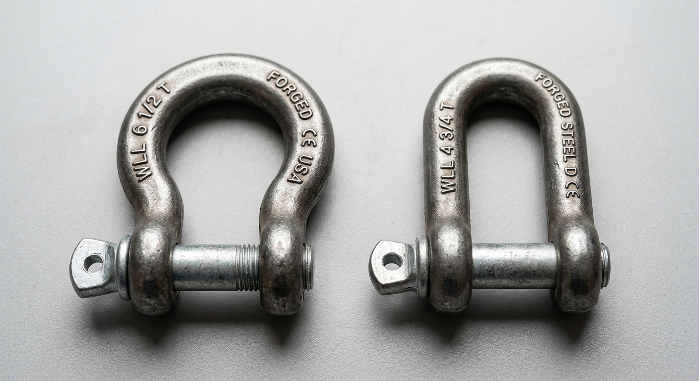
The defining difference between a bow shackle and a D shackle is not size — it is internal geometry. A zaczep łukowy (also called an anchor shackle) features a rounded, omega-shaped body with a significantly wider internal width relative to pin diameter. This expanded internal space is not aesthetic; it directly increases the angular freedom available to attached hardware and allows multiple sling legs to seat against the curved crown without mutual interference.
A D shackle (dee shackle) has a narrow, straight-sided body that closely mirrors the letter “D.” The internal width is deliberately constrained, which keeps the load path tightly aligned with the pin axis. This geometry is optimized for in-line, single-connection applications where the load vector remains predictable and perpendicular to the pin.
The pin-to-crown distance is proportionally greater in bow shackles, which increases the moment arm available for load distribution across the crown radius. In D shackles, the shorter pin-to-crown distance concentrates stress at a tighter point, making them efficient under axial tension but less tolerant of angular deviation.
1.2 Pin Design and Load Bearing Axis
Both bow and D shackles are available with screw pin or bolt-type (safety pin) configurations. Screw pins allow faster rigging and de-rigging, making them common in construction and general lifting. Bolt-type pins with nuts and cotter pins are specified for permanent or semi-permanent installations, offshore applications, and anywhere vibration could back out a screw pin.
Critically, the shackle body shape governs load bearing axis tolerance more than pin type does. Bow shackles tolerate multi-directional loading — loads can approach from various angles within the plane of the bow without inducing severe stress concentrations. D shackles are designed for single-axis loading along the line of the body. Any lateral or angular force applied to a D shackle constitutes side-loading, which can reduce effective WLL by 50% or more depending on the angle and the manufacturer’s derating curve.
| Parameter | Bow Shackle | D Shackle |
|---|---|---|
| Body Shape | Rounded / Omega | Straight-sided / Dee |
| Internal Width | Wide | Narrow |
| WLL Range (typical) | 0.5t – 150t+ | 0.3t – 120t+ |
| Load Direction Tolerance | Multi-directional | In-line only |
| Multi-Leg Sling Compatibility | Yes (2–3 legs) | No (single connection) |
| Typical Application | Multi-leg rigging, marine, offshore | Inline lifting, single sling attachment |
| Standard Compliance | EN 13889, ASME B30.26 | EN 13889, ASME B30.26 |
| Pin Options | Screw pin / Bolt-type | Screw pin / Bolt-type |
2. Performance in Real Lifting Applications
2.1 Sling Clearance and Multi-Leg Rigging
The bow shackle’s wider body is the primary reason it dominates multi-leg rigging configurations. When a three-leg chain sling or a bridle arrangement connects to a single master link or hook, the bow shackle acts as the consolidation point. Its curved internal profile provides enough lateral clearance for two or three sling legs to hang without crossing, binding, or inducing unintended angular loads on the pin.
D shackles cannot safely perform this function. The narrow internal width forces sling legs into contact with the pin rather than the body crown, creating point-loading conditions that the pin is not rated to handle. Rigging standards and manufacturer documentation consistently restrict D shackles to one sling leg per connection point. Attempting to rig multiple slings through a D shackle is a recognized misuse that has contributed to documented field failures.
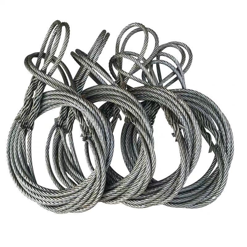
Sling clearance also matters at the termination end. When wire rope slings with swaged ferrule eyes connect to a bow shackle, the wider internal width accommodates the ferrule diameter without forcing the eye to ride up the pin threads — a common issue with undersized D shackles that accelerates pin wear and complicates visual inspection.
2.2 Load Direction Sensitivity and Side-Loading Risk
Side-loading is one of the most underreported risk factors in shackle failure. A shackle subjected to a side load — any force not aligned with the intended load axis — experiences bending stress in the body that its WLL rating does not account for. The D shackle’s straight-sided geometry makes it particularly vulnerable: even a 5–10° angular deviation from the in-line axis begins to introduce bending moments.
Bow shackles are inherently more forgiving under angular loading because the curved body distributes stress across a larger cross-sectional arc. In dynamic lifts — crane picks over water, load transfers on sloped surfaces, or suspended loads subject to pendulum motion — the bow shackle’s geometry maintains better load path integrity as the angle of pull shifts.
That said, no shackle is immune to side-loading damage. ASME B30.26 and most manufacturer guidelines require that shackles used in conditions where side-loading is anticipated be specifically rated for that condition, with appropriate derating applied to the WLL.
3. Compliance Standards and WLL Specifications
3.1 Applicable International Standards
Both bow shackles and D shackles fall under the scope of EN 13889 (European standard for forged steel shackles for general lifting purposes) and ASME B30.26 (American standard for rigging hardware). These standards define minimum design factors, proof load requirements, and marking obligations — but they also contain shape-specific usage guidance that directly affects specification decisions.
EN 13889 classifies shackles by grade: Grade 6 (design factor 6:1) and Grade 8 (design factor 8:1). Higher-grade shackles offer greater safety margins at equivalent WLL ratings and are increasingly specified for offshore and critical lift applications. The standard explicitly references the body shape when defining acceptable connection configurations, reinforcing that bow and D shackles are not interchangeable across all use cases.
ASME B30.26 additionally addresses angular load derating, providing guidance on WLL reduction when shackles are used outside their rated load axis. Procurement specifications referencing ASME B30.26 should explicitly state the expected load angle range so that suppliers can confirm compliance.
3.2 Proof Load, WLL Marking, and Traceability Requirements
Every compliant shackle must carry permanent markings that include: manufacturer identification, WLL (in tonnes or equivalent), grade designation, and traceability code. EN 13889 requires that these markings be applied to the body — not the pin — since pins are replaceable components and must be separately traceable.
For procurement audit compliance, purchase orders should request:
- Material test certificates (MTC) to EN 10204 3.1 or 3.2, confirming alloy composition and mechanical properties
- Proof load test records — typically 2× WLL for Grade 6, applied before delivery
- Dimensional inspection reports confirming body and pin geometry against the declared standard
- Marking photographs or physical inspection access prior to shipment for high-volume orders
Accepting shackles without full documentation creates traceability gaps that can invalidate lifting equipment registers during third-party audits or incident investigations.
4. Selecting the Right Shackle: Application-Driven Decision Criteria
4.1 Connection Options and Hardware Compatibility
Bow shackles connect reliably to a broader range of hardware: master rings, crane hooks, wire rope sling eyes, chain links, and pad eyes — including those with irregular geometry or larger bore diameters. The wider internal opening reduces the risk of the connected hardware riding off-center on the pin, which is a common cause of accelerated wear.
D shackles are the preferred choice when connecting to narrow-bore pad eyes, clevis attachments, or single wire rope terminations where a precise, tight fit is required to prevent lateral movement. The constrained internal width of a D shackle actually becomes an advantage in these configurations, preventing the load from shifting along the pin axis during the lift.
Hardware compatibility also extends to hook throat clearance. In overhead crane applications where the shackle must pass through or seat within a hook, the D shackle’s slimmer profile can be the deciding factor in fit — provided the load path remains in-line.
4.2 Industry-Specific Use Cases
Offshore and marine rigging strongly favors bow shackles, particularly bolt-type Grade 8 configurations. Multi-leg sling arrangements, dynamic sea-state loading, and the requirement for full traceability under DNV or LOLER frameworks all align with the bow shackle’s design strengths.
Overhead crane lifting in manufacturing and warehousing uses both types: bow shackles at the master link position for multi-leg lifts, D shackles for direct single-point connections to lifting eyes machined into equipment.
Construction and civil engineering applications often use screw-pin bow shackles for their combination of flexibility and speed — the wider body accommodates varied connection hardware encountered across a project site.
Marine deck hardware and mooring applications favor bow shackles with bolt-type pins secured by mousing wire, where vibration and cyclic loading would otherwise back out a screw pin over time.
Najczęściej zadawane pytania
Q1: Can a bow shackle be used as a direct replacement for a D shackle at the same WLL rating?
Not without reviewing the connection geometry. At equivalent WLL, a bow shackle’s wider body may not fit a narrow pad eye or clevis designed around D shackle dimensions. Confirm bore diameter and jaw width compatibility before substituting. Functionally, the bow shackle is the safer choice for multi-directional loads, but dimensional fit must be verified.
Q2: What is the maximum number of sling legs that should be attached to a bow shackle pin?
Industry guidance and most manufacturer specifications limit connections to the bow shackle body (crown), not the pin. The pin itself should carry only one sling leg or connecting element. The bow shackle body can accommodate two to three sling legs across the crown, but the pin should remain a single-connection point to avoid bending loads.
Q3: How do I verify that a shackle meets EN 13889 or ASME B30.26 before accepting delivery?
Request the material test certificate (EN 10204 3.1 minimum), proof load test records, and dimensional inspection report from the supplier. Confirm that body markings include WLL, grade, and manufacturer identification. For critical applications, specify third-party inspection by an accredited body (e.g., Bureau Veritas, Lloyd’s Register) as a purchase order condition.
Podsumowanie
Shackle shape is not a cosmetic specification — it defines load path integrity, sling clearance, and compliance alignment in every lifting operation. The bow shackle’s wider internal geometry makes it the correct choice for multi-leg rigging, angular loading conditions, and applications requiring connection flexibility across varied hardware. The D shackle’s constrained profile delivers precision fit and efficient in-line load transfer for single-connection, axially loaded applications.
Procurement teams that match shackle geometry to application requirements — and enforce documentation standards at the point of order — reduce rigging failure risk, simplify inspection workflows, and maintain audit-ready lifting equipment registers. Specify by shape, grade, and standard. Do not treat bow and D shackles as interchangeable components.