

1. What Is a Pressed Wire Rope Sling?
1.1 Core Construction & Materials
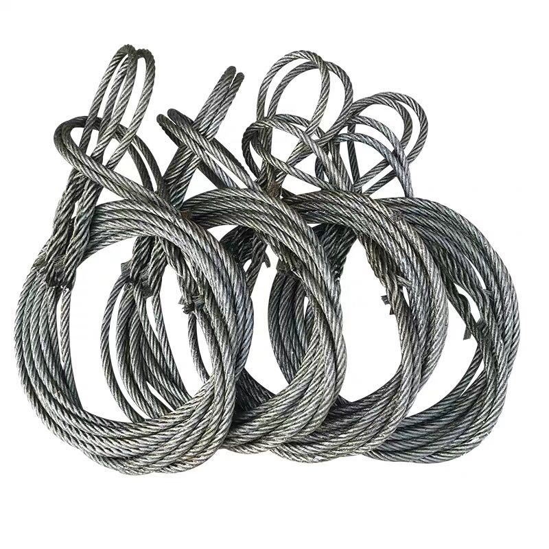
A pressed wire rope sling is an engineered lifting assembly built around a multi-strand wire rope core, terminated at one or both ends using mechanically pressed ferrules. The rope itself typically follows a 6×19 or 6×37 strand configuration—six outer strands helically wound around a central core, which may be an independent wire rope core (IWRC) or a fiber core (FC). IWRC variants deliver superior crush resistance and higher breaking force, making them the preferred choice for heavy industrial lifting.
Material selection is application-driven. High-carbon steel wire (minimum tensile grade 1570 MPa or 1770 MPa) dominates general-purpose lifting due to its optimal balance of strength, flexibility, and cost. For corrosive environments—offshore platforms, chemical plants, marine terminals—316L stainless steel wire rope provides superior resistance to chloride-induced pitting and oxidation without significant loss of tensile performance. Galvanized wire rope represents a cost-effective middle ground, offering enhanced corrosion protection while retaining the mechanical properties of carbon steel.
The rope’s lay direction (right-hand ordinary lay or Lang’s lay) and wire surface finish (bright, galvanized, or stainless) are specified based on the operational environment and the type of sheave or drum contact expected during use.
1.2 Ferrule Termination: How the Press Fitting Works
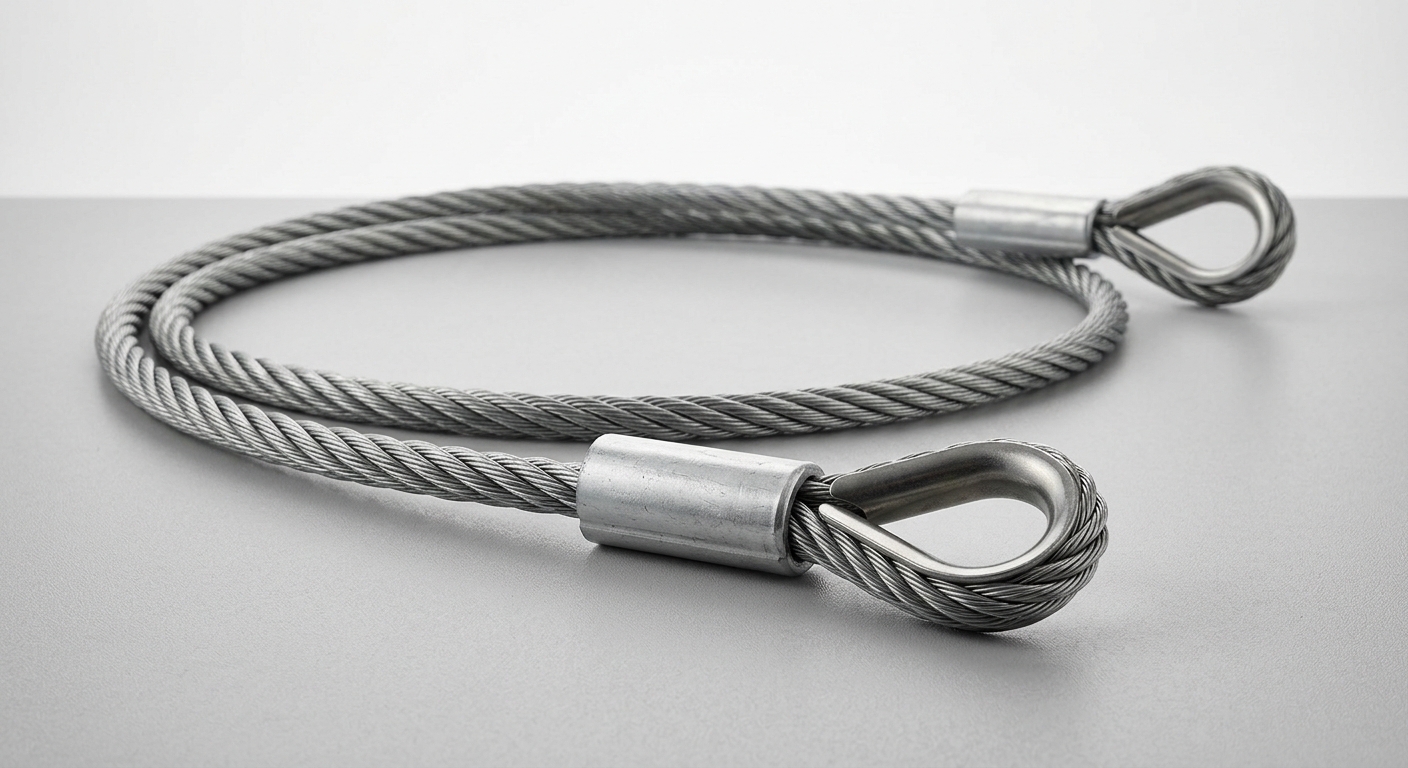
The defining feature of a pressed wire rope sling is its cold-press ferrule termination. The rope end is threaded through an aluminum or steel ferrule sleeve, looped back to form an eye, and then compressed under hydraulic pressure—typically 200–400 kN depending on rope diameter. This cold-swaging process deforms the ferrule material into the wire interstices, creating a mechanical interlock that transfers load through friction and bearing contact across the entire compressed zone.
The result is a termination efficiency of 95–100% of the rope’s minimum breaking force (MBF)—significantly superior to hand-spliced or mechanically swaged clip terminations, which typically achieve 80–90% efficiency. Unlike spliced eyes, ferrule terminations eliminate the risk of strand pullout under shock loading and require no specialist braiding skill to produce consistently. The pressed joint is also dimensionally compact, allowing the sling to pass through tight rigging configurations where a bulky splice would obstruct clearance.
2. Key Technical Specifications & Selection Parameters
The table below summarizes standard pressed wire rope sling parameters across common diameter ranges:
| Rope Diameter (mm) | Min. Breaking Force (kN) | WLL – Single Leg (t) | WLL – 2-Leg 60° (t) | WLL – 4-Leg 60° (t) | Angle Efficiency Factor |
|---|---|---|---|---|---|
| 8 | 38.0 | 0.75 | 1.30 | 2.60 | 0.87 |
| 12 | 84.0 | 1.60 | 2.77 | 5.54 | 0.87 |
| 16 | 148.0 | 2.80 | 4.85 | 9.70 | 0.87 |
| 20 | 231.0 | 4.25 | 7.36 | 14.72 | 0.87 |
| 28 | 446.0 | 8.50 | 14.72 | 29.44 | 0.87 |
| 36 | 736.0 | 14.00 | 24.25 | 48.50 | 0.87 |
WLL calculated at a 5:1 safety factor per EN 13414-1. Angle efficiency factor applies at a 60° included angle.
2.1 Diameter, WLL & Safety Factor
Standard pressed wire rope slings are commercially available from 6 mm through 64 mm nominal diameter, covering working load limits (WLL) from approximately 0.5 t to over 100 t for multi-leg configurations. The WLL is derived by dividing the rope’s minimum breaking force by the design factor—universally set at ≥ 5:1 under EN 13414, ASME B30.9, and AS 3569. This means a sling with a 250 kN MBF carries a single-leg WLL of 5.0 t.
Buyers must specify WLL—not breaking strength—on purchase orders. Confusing the two is a common procurement error that creates latent safety risk. Always confirm that the manufacturer’s test certificate references the applicable design factor and that the marked WLL on the ferrule or attached tag matches the intended load.
2.2 Sling Configuration & Angle Efficiency
Single-leg slings carry 100% of the rated WLL vertically. When two or four legs are rigged to a master link, the shared load capacity increases—but only if the included angle between legs is controlled. At a 60° included angle, each leg carries 87% of its rated capacity; at 90°, this drops to 71%; at 120°, efficiency falls to just 50%.
Practical implication: a 4-leg sling rated at 10 t per leg does niet lift 40 t at wide angles. Riggers must calculate the resultant leg tension based on actual geometry before each lift. Most manufacturers supply angle correction charts with their sling documentation; procurement teams should confirm these charts are included in the product delivery package.
3. Compliance Standards & Quality Inspection
3.1 Applicable International Standards
Three standards govern pressed wire rope sling design, manufacture, and testing across major global markets:
- EN 13414-1/2 (Europe): Specifies WLL calculation, ferrule termination efficiency requirements, marking, and proof load testing at 2× WLL. CE marking is mandatory for slings placed on the EU market under the Machinery Directive 2006/42/EC.
- ASME B30.9 (North America): Covers sling design factors, inspection intervals, and rejection criteria. OSHA 29 CFR 1910.184 references B30.9 for general industry compliance.
- ISO 2408: Defines wire rope construction parameters (strand count, wire diameter tolerances, lay length) that underpin sling assembly quality.
Compliant slings must display: manufacturer identity, WLL (in tonnes or lbs), rope diameter, applicable standard, and a unique batch/serial number traceable to the test certificate. Buyers sourcing from overseas suppliers should request third-party proof load test certificates from accredited laboratories—not in-house test reports alone.
3.2 Pre-Use Inspection & Rejection Criteria
EN 13414 and ASME B30.9 both mandate documented pre-use inspection. Mandatory discard conditions include:
- Broken wires: ≥ 10 randomly distributed broken wires in any rope lay length, or ≥ 5 broken wires in one strand
- Ferrule deformation: Any cracking, splitting, or visible slippage of the wire through the pressed sleeve
- Diameter reduction: > 10% reduction from nominal diameter indicating internal core failure
- Corrosion: Surface pitting that removes more than 10% of individual wire cross-section, or any inter-strand corrosion
- Kinking, crushing, or birdcaging: Any permanent geometric deformation of the rope structure
- Heat damage: Discoloration, annealing, or weld spatter contact marks
Slings meeting any single rejection criterion must be removed from service immediately and destroyed to prevent re-use.
4. Industrial Application Scenarios & Commercial Value
4.1 Typical Heavy Lifting Use Cases
Pressed wire rope slings are the default lifting medium across capital-intensive industries where load integrity and service life are non-negotiable:
- Shipbuilding & marine fabrication: Block assembly lifts of 50–500 t require slings that resist abrasion from hull plate edges and tolerate salt-spray exposure—galvanized or stainless IWRC slings are standard.
- Steel structure erection: Column and beam lifts in high-rise construction demand precise WLL documentation for crane load charts; ferrule terminations provide the consistent geometry required.
- Petrochemical & refinery: Pressure vessel and heat exchanger installation in H₂S environments mandates stainless steel slings with documented material traceability certificates.
- Port & container terminal operations: High-cycle crane spreader rigging benefits from the fatigue resistance of IWRC rope and the dimensional repeatability of pressed eyes over spliced alternatives.
In environments above 100°C, synthetic fiber slings are disqualified; wire rope slings remain operational up to 400°C (with reduced WLL above 200°C per EN 13414).
4.2 Total Cost of Ownership vs. Alternative Slings
| Parameter | Pressed Wire Rope | Synthetic Webbing | Alloy Chain |
|---|---|---|---|
| Initial Unit Cost | Medium | Low | High |
| Service Life (cycles) | 5,000–20,000+ | 500–2,000 | 10,000+ |
| Abrasion Resistance | High | Low | Very High |
| Chemical Resistance | Medium–High (SS) | Low–Medium | Medium |
| UV Degradation | None | Significant | None |
| Inspection Simplicity | Moderate | Easy | Moderate |
Wire rope slings deliver the best cost-per-lift ratio in medium-to-heavy industrial applications where synthetic slings wear out rapidly and chain slings impose excessive weight penalties on mobile crane capacity. For bulk procurement—typically 50+ slings per order—manufacturers offer custom eye configurations, thimble types, and protective sleeves at volume pricing, further reducing lifecycle cost.
Veelgestelde vragen
Q1: What is the maximum rated capacity for a single-leg pressed wire rope sling, and how does the lifting angle affect the WLL?
Single-leg pressed wire rope slings in standard commercial production reach WLLs exceeding 100 t for 64 mm diameter rope. However, the moment a sling is rigged at an angle from vertical, the effective WLL decreases. At 45° from vertical (90° included angle), the leg tension factor is 0.71—meaning a 10 t rated sling can only safely contribute 7.1 t to the lift. Always use the manufacturer’s angle correction table and never exceed 120° included angle between legs.
Q2: How do I verify that a pressed wire rope sling meets EN 13414 or ASME B30.9 compliance before use?
Request the product’s Declaration of Conformity (DoC) for CE-marked slings, or the manufacturer’s test certificate referencing ASME B30.9 for North American supply. Each sling must carry a permanent identification tag showing WLL, rope diameter, applicable standard, and batch number traceable to proof load test records. Third-party verification from accredited bodies (e.g., Lloyd’s, Bureau Veritas, TÜV) provides the highest assurance level for critical lifts.
Q3: What are the mandatory discard criteria for a pressed wire rope sling with ferrule termination?
Discard immediately if you observe: 10 or more broken wires per lay length, any cracking or slippage at the ferrule, diameter reduction exceeding 10%, corrosion pitting removing more than 10% of wire cross-section, or any kinking, crushing, or heat damage. The ferrule joint specifically must show zero visible deformation—even hairline cracks in the sleeve indicate termination failure and require immediate withdrawal from service.
Conclusie
A pressed wire rope sling combines high-carbon or stainless steel multi-strand rope construction with hydraulically swaged ferrule terminations to deliver consistent, verifiable lifting capacity across the most demanding industrial environments. The 95–100% termination efficiency of cold-pressed ferrules, combined with traceable WLL documentation under EN 13414 or ASME B30.9, makes this sling type the technically preferred solution for shipbuilding, petrochemical, structural steel, and port operations.
Selecting the correct diameter and configuration requires understanding the relationship between rope MBF, the 5:1 design factor, and the geometric angle efficiency that governs multi-leg assemblies. Procurement teams should specify compliance standards, material grade, eye configuration, and required test documentation at the point of purchase—not after delivery.
For operations requiring long service intervals, corrosion resistance, and full regulatory traceability, the pressed wire rope sling offers a lower total cost of ownership than synthetic or chain alternatives across most medium-to-heavy lifting profiles.