

Abstract
Wire rope fatigue is one of the most consequential and preventable failure modes in lifting, rigging, and material handling systems. Unlike sudden overload fractures, bending fatigue develops progressively—accumulating micro-damage through thousands of load cycles before visible degradation appears. For procurement and engineering teams, this makes early-stage identification and construction-based prevention critical to operational safety and cost control.
Rondstreng staalkabel, the dominant configuration across industrial applications, offers meaningful design variables that directly influence fatigue resistance: wire count per strand, core type, lay direction, and diameter classification. Understanding how these variables interact with external operating conditions—sheave geometry, fleet angle, load frequency—enables informed selection decisions that extend service life, reduce unplanned downtime, and lower total cost of ownership.
This article provides a structured technical framework for evaluating bending fatigue in round-strand wire rope, covering failure mechanics, construction comparisons, compliance benchmarks, and a practical procurement checklist for high-cycle applications.
1. The Mechanics of Bending Fatigue in Wire Rope
1.1 How Repeated Bending Initiates Wire Fatigue
Bending fatigue in wire rope originates at contact points—specifically where individual wires press against adjacent wires and against the sheave groove surface during each load cycle. As the rope bends over a sheave, outer wires experience tensile stress on the convex side and compressive stress on the concave side. This alternating stress state, repeated across thousands of cycles, initiates microscopic fatigue cracks at stress concentration zones.
The dominant damage mechanism is inter-wire fretting: relative micro-movement between contacting wires generates surface abrasion and fretting debris, which acts as an abrasive medium and accelerates crack nucleation. Once a fatigue crack propagates through a wire’s cross-section, the load redistributes to adjacent wires, accelerating failure progression across the entire strand. In high-cycle applications, this cascade can reduce rope breaking strength by 30–50% before any visible external damage is apparent—making routine inspection protocols essential.
1.2 Key Variables That Accelerate Fatigue Failure
Multiple operating variables interact to determine the rate of fatigue accumulation. The D/d ratio (sheave diameter to rope diameter) is the single most influential mechanical parameter: lower ratios impose sharper bending angles, increasing bending stress per cycle. Fleet angle misalignment causes the rope to enter the sheave groove at an oblique angle, generating lateral contact forces that accelerate groove wear and uneven wire loading. Dynamic load fluctuation—common in crane hoisting cycles—compounds fatigue by introducing variable stress amplitudes that prevent stress stabilization.
| Variable | Low-Fatigue Condition | High-Fatigue Condition | Impact Level |
|---|---|---|---|
| D/d Ratio | ≥ 40:1 | < 20:1 | Critical |
| Fleet Angle | < 1.5° | > 4° | High |
| Load Cycle Frequency | Low, consistent loads | High-frequency variable loads | High |
| Lubrication State | Fully lubricated | Dry or contaminated | Moderate–High |
| Rope Construction | High wire count, IWRC | Low wire count, FC | Moderate |
Lubrication state is frequently underestimated: a well-lubricated rope reduces inter-wire friction, limits fretting debris generation, and provides corrosion protection that preserves wire cross-section integrity over time.
2. Round-Strand Construction: Fatigue Resistance by Design
2.1 Strand Geometry and Wire Count: How Construction Affects Flexibility
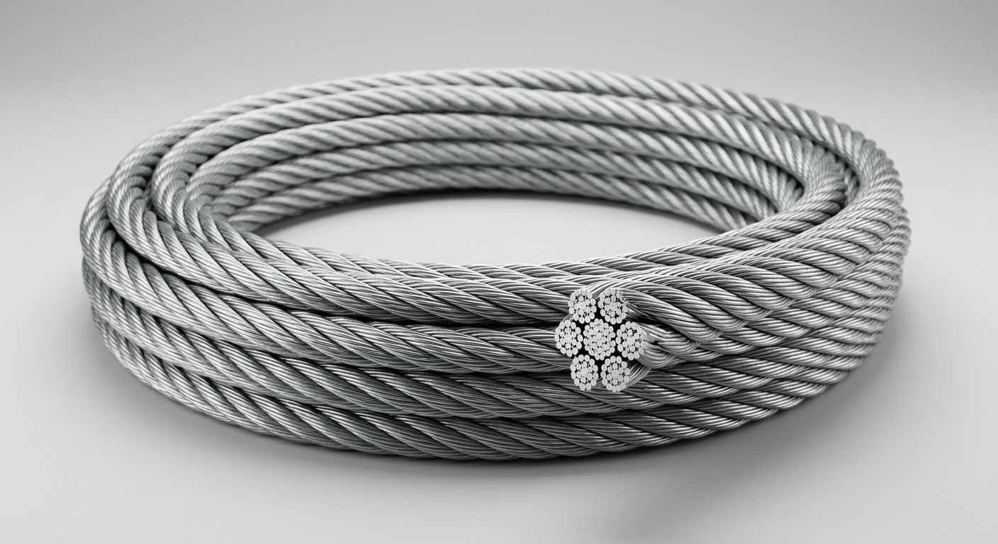
Round-strand wire rope classifications—6×19, 6×36, 8×19 class—differ primarily in the number of wires per strand, which directly determines individual wire diameter for a given rope diameter. This relationship is critical to fatigue performance: smaller-diameter wires bend more easily, experiencing lower bending stress per cycle when the rope passes over a sheave.
- 6×19 class (15–26 wires per strand): Larger individual wires provide higher abrasion resistance but lower bending flexibility. Preferred for applications with high D/d ratios and moderate cycle counts.
- 6×36 class (27–49 wires per strand): Finer wires offer significantly improved bending fatigue resistance. The preferred configuration for high-cycle overhead crane and hoist applications.
- 8×19 class: The additional strand count (8 vs. 6) increases rope flexibility and distributes contact stress across a larger surface area, further reducing fatigue accumulation per cycle.
For procurement teams, the selection trade-off is clear: higher wire counts improve fatigue life but reduce crush resistance. Matching construction class to the dominant failure mode of the application—fatigue versus mechanical damage—is the primary selection criterion.
2.2 Core Type and Lay Direction: Structural Contributions to Fatigue Life
The rope core provides radial support to outer strands during bending. An Independent Wire Rope Core (IWRC) maintains strand geometry under load, preventing strand collapse and reducing inter-wire contact pressure during bending cycles. Compared to a Fiber Core (FC), IWRC-cored ropes demonstrate measurably superior fatigue life in high-cycle bending applications—the fiber core compresses under load, allowing strands to migrate inward and increasing inter-strand contact stress.
Lay direction also influences fatigue behavior under cyclic stress:
- Regular lay (wires laid opposite to strand direction): Higher resistance to crushing and kinking; preferred where mechanical damage risk is elevated.
- Lang’s lay (wires laid in the same direction as strands): Greater wire-to-sheave contact area reduces contact stress per unit length, yielding improved bending fatigue resistance in controlled, properly aligned systems. However, Lang’s lay is more susceptible to rotation and requires secure end terminations.
For high-cycle, well-aligned systems such as overhead cranes and winches, a 6×36 IWRC Lang’s lay configuration typically delivers the highest bending fatigue resistance within the round-strand category.
3. Compliance Standards and Minimum Performance Benchmarks
3.1 Relevant International Standards for Wire Rope Fatigue Testing
Three primary standards frameworks govern wire rope fatigue performance and minimum design requirements:
- ISO 17893: Defines terminology and mechanical testing requirements for steel wire ropes, including fatigue test cycle methodologies and minimum breaking force classifications.
- EN 12385-4: The European standard for stranded steel wire ropes for general lifting applications, specifying minimum D/d ratios by rope construction class and load category.
- ASME B30 series: Governs overhead and gantry cranes in North American jurisdictions, establishing minimum sheave diameter requirements and inspection frequency protocols tied to operational severity classifications.
These standards establish the minimum D/d ratios that prevent accelerated fatigue—typically 16:1 for 6×36 class ropes in standard duty, rising to 26:1 or higher for severe-duty classifications. Procurement specifications should reference the applicable standard explicitly and require supplier documentation of compliance testing.
3.2 Inspection Intervals and Discard Criteria Under Regulatory Frameworks
Regulatory discard criteria provide objective thresholds for retirement decisions, removing subjective judgment from the inspection process:
- Broken wire count: EN 12385-4 and ASME B30.2 specify maximum allowable broken wires per rope lay length (typically 6 random broken wires in one rope lay, or 3 in one strand) before mandatory discard.
- Diameter reduction: A reduction exceeding 3% of nominal diameter from external wear, or 1% from internal deterioration, typically triggers discard.
- Corrosion: Surface pitting, rust penetration into the core, or evidence of stress corrosion cracking are independent discard triggers regardless of broken wire count.
Inspection intervals should be calibrated to operational severity—high-cycle crane applications may require weekly visual inspections supplemented by monthly detailed examinations under applicable standards.
4. Application Scenarios and Commercial Value of Fatigue-Optimized Selection
4.1 High-Cycle Applications Where Round-Strand Selection Drives ROI
Applications with the highest ROI sensitivity to rope construction selection include:
- Overhead cranes and hoists: Operating 200–500 cycles per shift, these systems accumulate fatigue rapidly. Upgrading from 6×19 FC to 6×36 IWRC can extend service intervals by 40–70%, reducing replacement frequency and crane downtime costs.
- Offshore winches and mooring systems: Corrosive environments compound fatigue mechanisms; IWRC construction with factory-applied penetrating lubricant provides dual protection.
- Draglines and mining hoists: High suspended loads combined with continuous cycling make construction optimization critical to both safety and operational continuity.
The commercial case is straightforward: a rope that costs 20–30% more per unit but delivers 50–70% longer service life reduces total rope expenditure while eliminating the indirect costs of unplanned maintenance windows.
4.2 Procurement Checklist: Matching Rope Construction to Operating Conditions
| Evaluation Criterion | Action Required |
|---|---|
| Load spectrum analysis | Document minimum, maximum, and dynamic load values; calculate fatigue index |
| Sheave condition audit | Verify groove diameter, profile condition, and D/d ratio compliance |
| Fleet angle measurement | Confirm alignment within standard limits before rope installation |
| Lubrication specification | Specify lubricant type, application method, and re-lubrication interval |
| Supplier certification | Require mill certificates, EN/ISO compliance documentation, and batch traceability |
| Inspection protocol | Define broken wire thresholds, inspection frequency, and discard decision authority |
Veelgestelde vragen
Q1: What is the minimum D/d ratio recommended to prevent premature bending fatigue in round-strand wire rope?
Most standards specify a minimum of 16:1 for standard-duty applications using 6×36 class rope, but severe-duty classifications under ASME B30 and EN 12385-4 require ratios of 26:1 to 40:1. Higher wire count constructions tolerate lower D/d ratios more effectively than coarser constructions. Always reference the applicable standard for your duty classification.
Q2: How does wire rope fatigue failure differ from overload failure, and how can procurement teams identify early warning signs?
Overload failure produces sudden, high-energy fracture with characteristic “birdcaging” or cup-and-cone wire breaks. Fatigue failure develops progressively: early indicators include broken wires concentrated at sheave contact zones, reduction in rope diameter, and increased wire surface roughness from fretting. Implementing standardized inspection logs that track broken wire counts over time allows teams to identify accelerating deterioration trends before failure occurs.
Q3: Does switching from a fiber core to an IWRC significantly extend wire rope service life in high-cycle bending applications?
Yes, measurably. IWRC maintains strand geometry under repeated bending loads, reducing inter-strand contact stress and slowing fatigue crack initiation. In controlled fatigue testing, IWRC ropes consistently demonstrate 20–40% longer fatigue life than equivalent FC configurations under identical bending conditions. For any application exceeding 100 cycles per shift, IWRC specification is strongly recommended.
Conclusie
Bending fatigue is not an inevitable consequence of wire rope use—it is a manageable engineering variable. Round-strand wire rope construction offers procurement and engineering teams multiple design levers: wire count, core type, lay direction, and diameter class each contribute measurably to fatigue resistance. When combined with proper sheave geometry, controlled fleet angles, consistent lubrication, and compliance-aligned inspection protocols, construction-optimized rope selection delivers quantifiable service life extension and reduced lifecycle cost.
The decision framework is clear: analyze the load spectrum, audit the mechanical system, specify construction to match the dominant failure mode, and enforce discard criteria rigorously. Teams that apply this structured approach consistently report fewer unplanned replacements, lower total rope expenditure, and improved operational safety margins across high-cycle lifting and rigging applications.