

Abstrak
Tali kawat untai bulat is the workhorse of lifting, rigging, and marine operations — environments where cyclic bending over sheaves and drums is not an occasional event but a continuous operational reality. Unlike static tension applications, repeated bending imposes a fundamentally different damage mechanism: fatigue. Fatigue failure is insidious because it accumulates invisibly inside the rope cross-section long before surface wire breaks become visible to inspectors.
This article provides a structured technical analysis for procurement engineers, rigging supervisors, and asset managers who need to make informed decisions about rope selection and lifecycle management. We examine the mechanical basis of bending fatigue, the construction parameters that either accelerate or resist fatigue damage, the operating variables that define safe system design, and the maintenance protocols that translate to measurable service life extension. References to ISO 4309, ASME B30.2, and EN 12385-4 provide a compliance framework throughout.
1. The Mechanics of Bending Fatigue in Wire Rope
1.1 How Repeated Bending Generates Fatigue Damage
When round-strand wire rope bends over a sheave or drum, each individual wire within each strand undergoes a complex combination of bending stress, contact stress, and relative micro-movement against neighboring wires. This relative movement — known as inter-wire fretting — is the primary engine of fatigue damage.
At every wire-to-wire contact point, cyclic loading creates stress concentrations that far exceed the nominal rope tension. Under repeated bending, these localized stress peaks initiate micro-cracks at the wire surface, typically at contact flats where fretting has already abraded the protective wire surface. The cracks propagate perpendicular to the wire axis through successive load cycles in a process governed by fracture mechanics: slow and stable at first, then accelerating as the remaining wire cross-section shrinks and local stress intensity increases.
Three factors amplify this process:
- High contact stress between wires at small sheave diameters compresses contact zones and accelerates fretting debris generation
- Lubrication depletion removes the film that separates wire surfaces, increasing metal-to-metal friction and fretting severity
- Corrosive environments (particularly marine chloride exposure) accelerate crack propagation through corrosion-fatigue interaction, where electrochemical attack and mechanical fatigue act synergistically
The cumulative result is progressive strength loss that is not detectable through routine visual inspection until late-stage wire breaks emerge at the rope surface.
1.2 Key Failure Modes Caused by Bending Cycles
Bending fatigue produces failure signatures that are diagnostically distinct from tensile overload. Understanding these patterns enables accurate post-incident root cause analysis.
Crown wire breaks occur on the outer surface of strands at the point of maximum bending stress. Wire ends exhibit a classic fatigue fracture morphology: a flat, granular fracture face with beach marks (fatigue striations) visible under magnification, terminating in a small final-fracture zone. This contrasts sharply with tensile overload fractures, which show a cupped-and-cone or chisel-point morphology indicating ductile failure.
Valley wire breaks develop between strands, driven by inter-strand contact stress under bending. These are particularly dangerous because they are invisible during external visual inspection and can only be detected by magnetic rope testing (MRT) equipment or by opening the rope during discard-condition assessment.
Internal fatigue fracture in IWRC (independent wire rope core) ropes can progress significantly before any external indication appears. In high-cycle crane applications, ropes have been documented at 60–70% of their discard-condition broken wire count internally while appearing serviceable externally — a critical argument for instrument-based inspection in high-consequence lifts.
2. Construction Variables That Govern Fatigue Resistance
2.1 Strand Configuration, Wire Count, and Core Type
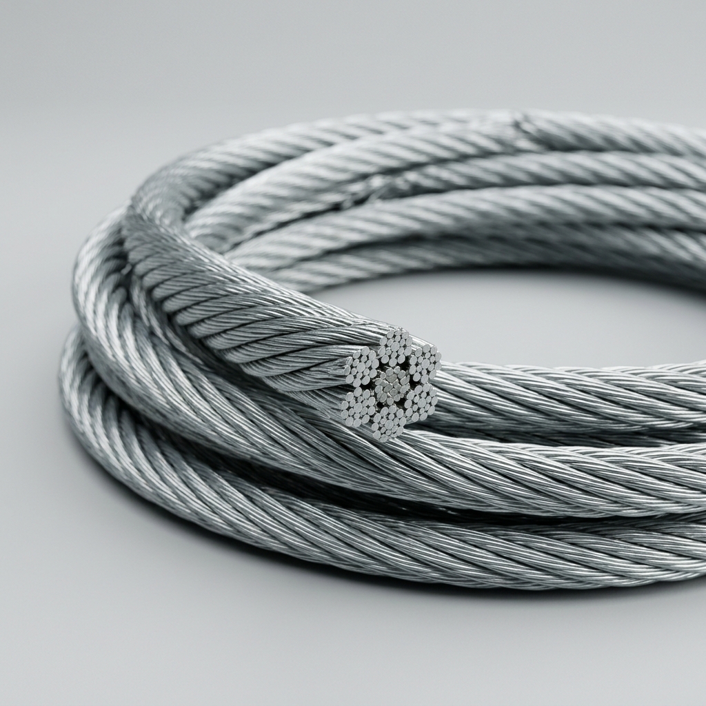
Round-strand rope construction is the single most consequential variable in fatigue performance. The fundamental trade-off is between wire diameter and wire count: fewer, thicker wires (e.g., 6×7 construction) offer high abrasion resistance but poor bending fatigue life because each wire carries a larger bending stress per cycle. More, thinner wires (e.g., 6×36 or 8×19 Seale) distribute bending stress across a larger number of contact points, reducing the stress amplitude at each wire and extending fatigue life substantially.
Core type also plays a significant role. An IWRC (Independent Wire Rope Core) maintains rope diameter stability under radial load from sheave contact, reducing strand distortion and inter-wire contact stress compared to a Fiber Core (FC). However, FC ropes offer greater flexibility and energy absorption, which can be advantageous in applications where rope-to-sheave conformity reduces peak contact stress.
Eight-strand constructions (e.g., 8×19) provide improved fatigue resistance over equivalent 6-strand ropes of the same diameter due to shorter strand lay length and more favorable bending geometry over sheaves.
2.2 Lay Type, Surface Finish, and Lubrication
Lang’s lay — where wires in each strand are laid in the same direction as the strands themselves — produces a longer wire contact length on sheave surfaces, distributing contact stress over a larger area and delivering measurably better bending fatigue life than regular lay rope under equivalent conditions. Lang’s lay is preferred for single-layer drum winding and where rotation is controlled. It is not suitable for free-hanging single-part lines due to rotation instability.
Surface finish affects both corrosion resistance and fatigue initiation. Bright (uncoated) wire provides maximum metallic cross-section but no corrosion protection. Drawn-galvanized wire (zinc coating applied before drawing) offers a thinner, harder zinc layer that maintains fatigue performance while improving corrosion resistance — the preferred choice for marine and offshore applications. Hot-dip galvanized wire, while offering heavier zinc coverage, can reduce fatigue life slightly due to hydrogen embrittlement risk during processing.
Factory lubrication applied during stranding and closing serves a dual function: it reduces inter-wire friction during bending cycles and provides a corrosion barrier at internal wire surfaces inaccessible to field re-lubrication. Lubrication retention under bending depends on lubricant viscosity and penetration depth — a critical factor in specifying rope for high-cycle applications.
📊 Construction Comparison Table
| Construction Type | Nominal Diameter Range | Wire Count | Recommended D/d Ratio | Relative Fatigue Life | Typical Application |
|---|---|---|---|---|---|
| 6×7 | 6–16 mm | 42 | ≥42 | Low | Standing rigging, guy wires |
| 6×19 (Seale/Warrington) | 8–40 mm | 114–133 | ≥26 | Medium | General crane hoist, hoisting blocks |
| 6×36 (Warrington-Seale) | 12–60 mm | 216 | ≥18 | High | High-cycle crane, offshore winch |
| 8×19 (Seale) | 16–52 mm | 152 | ≥16 | High | Elevator ropes, multi-layer drum |
D/d = sheave diameter to rope diameter ratio. Values based on ISO 4309 and manufacturer engineering data.
3. Operating Parameters and Compliance Standards
3.1 D/d Ratio, Fleet Angle, and Bending Frequency Limits
The sheave-to-rope diameter ratio (D/d) is the most critical system design parameter for fatigue life. As D/d decreases below the recommended minimum, bending stress per cycle increases exponentially — not linearly. ISO 4309 and ASME B30.2 publish minimum D/d values by rope classification and application; operating below these minimums can reduce rope service life by 50% or more per unit reduction in ratio.
For a 6×36 rope in a crane hoist application, a D/d of 18 is a practical minimum; increasing to 25 or 30 can double or triple fatigue cycle life under equivalent load conditions.
Fleet angle — the lateral deviation of the rope from the sheave groove centerline — introduces additional bending stress and accelerates groove wear. A fleet angle exceeding 2° for grooved drums or 1.5° for smooth drums generates measurable additional fatigue damage and should be corrected through system geometry adjustment.
Bending frequency affects fatigue life through two mechanisms: cycle accumulation (more cycles per unit time toward the fatigue limit) and thermal buildup in high-speed applications where viscous dissipation in the lubricant generates heat, reducing lubricant viscosity and inter-wire film thickness.
3.2 Applicable Standards and Discard Criteria
Three primary standards govern inspection and discard criteria for round-strand wire rope in service:
- ISO 4309:2017 — Cranes: wire ropes, care, maintenance, installation, examination, and discard. Defines broken wire count thresholds per rope length (expressed as multiples of rope diameter), corrosion ratings, and deformation criteria.
- ASME B30.2 — Overhead and Gantry Cranes: specifies discard criteria for visible wire breaks, kinking, crushing, and corrosion in North American jurisdictions.
- EN 12385-4 — Steel wire ropes for general lifting applications; defines construction requirements and minimum breaking forces.
Under ISO 4309, discard is typically triggered when broken wire count within any length of 6d or 30d exceeds the tabulated threshold for the specific rope classification — thresholds that are lower for rotation-resistant ropes and higher-factor-of-safety applications. High-cycle environments warrant inspection intervals measured in operating hours rather than calendar periods.
4. Maintenance Practices to Extend Fatigue Service Life
4.1 Lubrication Re-application and Rope Dressing Protocols
Factory lubrication is consumed by bending cycles through mechanical expulsion and by corrosive environments through chemical degradation. Field re-lubrication is not optional in high-cycle applications — it is a primary fatigue life management tool.
Two lubricant categories serve different functions:
- Penetrating lubricants (low-viscosity, solvent-carried) are designed to wick into the rope interior by capillary action, reaching inner wire surfaces where fatigue damage initiates. They are applied by immersion bath or pressure applicator and are most effective when applied to a clean, warm rope surface.
- Coating lubricants (high-viscosity, bituminous or grease-based) form a surface barrier against moisture and contaminants. They do not penetrate effectively but provide excellent environmental protection for ropes in marine splash zones.
In marine environments, corrosion-fatigue interaction means that lubrication frequency directly controls crack propagation rate — chloride ions accelerate fatigue crack growth at stress concentrations by factors of 2–5× compared to dry conditions. Re-lubrication intervals should be established based on bending cycle count (tracked by operation logs) rather than calendar time alone.
4.2 Inspection Methods and End-for-End Changeover Strategy
Visual inspection remains the baseline method: trained inspectors examine rope surface for broken wires, corrosion, kinking, birdcaging, and diameter reduction. However, visual inspection is fundamentally limited to external wire breaks and surface condition.
Magnetic Rope Testing (MRT) — also called Electromagnetic Inspection (EMI) — provides quantitative assessment of internal wire breaks and cross-sectional area loss. MRT instruments detect both Local Fault (LF) signals from discrete wire breaks and Loss of Metallic Area (LMA) from distributed corrosion or internal fatigue. For ropes in high-consequence crane and offshore applications, periodic MRT inspection is increasingly specified as a contractual requirement by asset owners and insurers.
End-for-end rope reversal is a cost-effective strategy for symmetric reeving systems: by reversing the rope orientation, the worn high-cycle zone (typically at the sheave contact point closest to the drum) is relocated to a lower-stress position, redistributing accumulated fatigue damage and extending total rope service life by 30–60% in documented crane applications.
All inspection findings, lubrication dates, and cycle counts should be recorded in a rope lifecycle log to support discard decisions, warranty claims, and incident investigation.
Pertanyaan yang Sering Diajukan
Q1: What is the minimum D/d ratio recommended for round-strand wire rope used in high-cycle crane applications?
For 6×36 or 8×19 constructions in high-cycle crane service, ISO 4309 recommends a minimum D/d of 18–20 as an absolute lower limit, with 25–30 recommended for optimized fatigue life. Operating below the minimum threshold accelerates fatigue damage non-linearly and should be avoided even when structurally feasible.
Q2: How can a procurement engineer distinguish bending fatigue failure from tensile overload failure during post-incident inspection?
Fatigue fractures display flat, granular fracture faces with visible beach marks (fatigue striations) and a small final-fracture zone — typically at 90° to the wire axis. Tensile overload fractures show ductile deformation: cupped-and-cone morphology, necking, and chisel-point wire ends. Fatigue failures also typically show multiple wire breaks distributed across a length equal to several rope diameters, while overload produces a concentrated, abrupt failure zone.
Q3: Does increasing wire count always improve fatigue resistance, or are there trade-offs?
Higher wire count reduces individual wire diameter, lowering bending stress per cycle and improving fatigue resistance. However, thinner wires are more susceptible to abrasion and corrosion pitting — both of which create stress concentrations that can initiate fatigue cracks. In highly abrasive environments, a moderate wire count construction (e.g., 6×19 Seale) may outperform a finer 6×36 rope in total service life despite lower theoretical fatigue resistance.
Kesimpulan
Round-strand wire rope fatigue performance is not a single-variable problem — it is the result of interaction between rope construction, sheave geometry, operating frequency, lubrication condition, and inspection discipline. No single parameter dominates in isolation: a correctly specified 6×36 IWRC rope will fail prematurely if operated on undersized sheaves; a well-engineered reeving system will not compensate for lubrication neglect in a marine environment.
Procurement and engineering teams that align rope selection with verified D/d ratios, adopt condition-based inspection schedules incorporating MRT for high-consequence applications, and apply structured re-lubrication protocols will achieve measurably longer service intervals and lower total cost of ownership. In demanding lifting and marine environments, the investment in correct specification and proactive maintenance consistently delivers returns that outweigh the cost of rope replacement on a reactive basis.