

Zusammenfassung
Side loading is one of the most frequently underestimated failure modes in rigging operations. While a Bogen-Schäkel is engineered to carry substantial axial loads, off-center or angular tension fundamentally alters the internal stress distribution — often reducing effective working load limit (WLL) by 25% to 50% or more before any visible deformation occurs.
This article addresses the mechanical principles behind side loading, quantifies WLL de-rating as sling leg angles increase, and translates compliance standards — including ASME B30.26, EN 13889, and OSHA 1926.251 — into practical procurement and field-rigging decisions. Whether you are specifying hardware for a multi-point crane lift or auditing supplier data sheets, understanding the relationship between angular load and shackle capacity is non-negotiable for structural safety and regulatory compliance.
The guidance here is directed at procurement engineers, rigging supervisors, and safety managers who need technically grounded criteria for selecting, rating, and inspecting bow shackles used in angled or multi-leg sling configurations.
1. The Mechanics of Side Loading on a Bow Shackle
How lateral and angular forces deviate from the bow shackle’s designed axial load path.
1.1 How Axial vs. Side Load Forces Differ Structurally
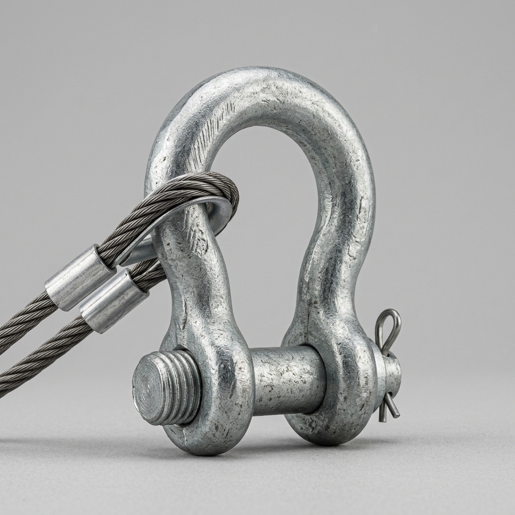
A bow shackle is designed so that tension travels in a straight axial line — from the pin centerline, through the bow body, and back to the pin. Under pure axial loading, stress distributes evenly across the bow’s cross-section, and the pin remains perpendicular to the applied force. This is the condition under which the manufacturer’s stated WLL is valid.
Side loading disrupts this geometry. When a sling leg pulls at an angle to the shackle’s vertical axis, the force resolves into two components: an axial component aligned with the intended load path, and a lateral component that bends the bow body sideways. This lateral component creates stress concentrations at the crown of the bow and at the pin-to-body interface — precisely the areas with the least material cross-section in most forged designs.
The consequences are progressive:
- Bow body deformation: The omega-shaped frame begins to distort, reducing its effective load-bearing cross-section.
- Pin rotation and walk: Off-axis tension causes the pin to rotate within its threads or cotter hole, increasing the risk of unintended disengagement.
- Fatigue crack initiation: Cyclic side loading accelerates micro-crack formation at stress concentration points, even when peak loads remain below the rated WLL.
1.2 Why the Bow (Omega) Shape Is Both an Advantage and a Vulnerability
The bow shackle’s wider, rounded body — often called the omega or anchor shape — provides a distinct advantage over dee shackle geometry when connecting multiple sling legs or wide-body fittings. The larger internal width accommodates thimbles, hooks, and multi-leg assemblies that would otherwise bear against a narrow dee frame.
However, this same geometry introduces a lateral flex tolerance limit. The wider the bow, the greater the moment arm when a side load is applied. A dee shackle, with its narrower profile, channels loads more directly through a shorter moment arm, making it inherently more resistant to lateral bending — though at the cost of reduced fitting compatibility.
For bow shackles, the practical implication is clear: the design accommodates angular connections but does not eliminate the WLL penalty that accompanies them.
2. How Multi-Leg Slings Reduce Bow Shackle Working Load Limit
Quantifying WLL de-rating as sling leg angle increases from 0° to 120°.
2.1 The Sling Angle–to–Capacity Reduction Relationship
The included angle between sling legs is the primary variable governing WLL de-rating. Industry standards and rigging engineering practice define three critical threshold zones:
- 0°–45° included angle: Load angle factor remains close to 1.0. WLL reduction is minimal (0–10%). This is the preferred operating range for any bow shackle in a multi-leg configuration.
- 45°–90° included angle: Load angle factor drops to approximately 0.71–0.87. WLL reduction ranges from 13% to 29%. Shackle upsizing is typically warranted.
- 90°–120° included angle: Load angle factor falls to 0.50–0.71. WLL reduction reaches 29%–50%. At 120°, each sling leg imposes a force equal to the full load weight — doubling the effective demand on the shackle relative to a vertical single-leg lift.
Beyond 120°, most standards prohibit the configuration entirely or require engineered lift plans with explicit hardware certification.
2.2 Practical Calculation: Determining Effective WLL Under Angled Load
The corrected WLL for a bow shackle in a multi-leg sling lift is calculated as:
Effective WLL = Rated WLL × Load Angle Factor
For a two-leg sling with a 90° included angle lifting a 4-tonne load:
- Load angle factor at 90° = 0.71
- Required shackle WLL = 4t ÷ 0.71 = 5.63 tonnes minimum
- Specify the next standard WLL class above this value (typically 6.5t or 8.5t, depending on the manufacturer’s range)
The safety factor embedded in the original WLL rating is not additive — it does not compensate for angular de-rating. The full safety factor must be preserved after applying the angle correction.
| Sling Included Angle | Load Angle Factor | WLL Reduction (%) | Minimum Recommended WLL Class | Notes |
|---|---|---|---|---|
| 0°–30° | 1.00–0.97 | 0–3% | Standard rated class | 2-leg / 4-leg: negligible correction |
| 30°–45° | 0.97–0.87 | 3–13% | Standard or one class up | Monitor pin alignment |
| 45°–60° | 0.87–0.71 | 13–29% | One class up minimum | Side-load inspection required |
| 60°–90° | 0.71–0.58 | 29–42% | Two classes up recommended | Pin locking mandatory |
| 90°–120° | 0.58–0.50 | 42–50% | Engineered lift plan required | Consider swivel hoist ring alternative |
3. Compliance Standards and Manufacturer Specifications
Regulatory frameworks governing side-load ratings for bow shackles.
3.1 Applicable Standards: ASME B30.26, EN 13889, and OSHA 1926.251
Three primary regulatory frameworks govern bow shackle side-load performance in industrial rigging:
ASME B30.26 (Rigging Hardware, USA) specifies that shackles shall not be used with loads applied to the side of the bow unless the manufacturer has rated the shackle for such use and that rating is documented. It distinguishes between proof load (typically 2× WLL) and the WLL itself, and mandates legible WLL marking on the shackle body.
EN 13889 (Forged Steel Shackles for General Lifting Purposes, Europe) requires manufacturers to state the permissible oblique pull angle on product documentation. The standard mandates a minimum safety factor of 4:1 against breaking load and requires that angular load ratings be validated through type testing — not extrapolated from axial test data alone.
OSHA 1926.251 (Rigging Equipment for Material Handling, USA construction) references manufacturer recommendations as the binding limit and requires that rigging hardware be inspected before each use. It does not define a specific angular de-rating formula but holds operators accountable for applying manufacturer-stated limits.
Collectively, these standards establish that the axial WLL stamped on a bow shackle is not valid for side-loaded applications without explicit manufacturer authorization and documented angular ratings.
3.2 Reading a Bow Shackle Data Sheet for Off-Center Load Ratings
When evaluating a supplier’s data sheet, procurement teams should verify the following:
- Angular load table or chart: Reputable manufacturers publish WLL values at multiple sling angles (typically 0°, 30°, 45°, 60°, 90°). Absence of this data is a disqualifying gap.
- Maximum permissible oblique angle: Many manufacturers cap side-load use at 45° or 60° without explicit engineered approval. This limit must appear in the product documentation.
- Traceability and certification: Request material certificates (EN 10204 3.1 or 3.2), proof load test records, and third-party certification (DNV, Bureau Veritas, Lloyd’s Register) for critical lifting applications.
- Pin type compatibility: Screw-pin shackles used under side loading require positive locking (moused wire, cotter pin, or safety bolt) to prevent pin rotation and walk.
4. Application Scenarios and Risk Mitigation in the Field
Where side loading commonly occurs and how to engineer it out.
4.1 High-Risk Rigging Configurations That Introduce Side Loading
Side loading is rarely intentional — it typically results from geometric constraints or planning oversights:
- Crane multi-point lifts: When a load’s center of gravity is offset from the crane hook centerline, sling legs adopt unequal angles, introducing side load into the apex shackle.
- Spreader bar misalignment: If a spreader bar’s attachment points are not aligned with the vertical load axis, the connecting bow shackles experience combined axial and lateral tension.
- Anchor point geometry errors: On structural anchors, a bow shackle connected to a plate or beam flange at an angle — rather than in-line with the sling — introduces immediate side loading from the first moment of tension.
In each scenario, the side load may not be visible during rigging setup but becomes structurally significant the instant the load is lifted.
4.2 Selection and Rigging Practices to Preserve Full WLL
Practical measures to eliminate or manage side loading:
- Upsize shackle WLL class: Apply the sling angle de-rating factor before specifying the shackle. Always select the next rated class above the calculated minimum.
- Use swivel hoist rings at anchor points: Where anchor geometry creates unavoidable angular loading, a swivel hoist ring self-aligns to the load direction, eliminating side load on the connection point entirely.
- Inspect for side-load damage indicators: After any lift with suspected angular loading, inspect the bow for lateral deformation, ovalization of the bow opening, and pin thread damage. Any visible distortion requires immediate removal from service.
- Document sling angles in lift plans: For engineered lifts, record the calculated included angle and the corresponding de-rated WLL in the lift plan. This creates an auditable compliance record under ASME B30.26 and OSHA requirements.
Häufig gestellte Fragen
1. What is the maximum allowable sling angle before a bow shackle must be upsized or replaced with a different connector?
Most manufacturers and standards treat a 60° included angle as the practical threshold requiring shackle upsizing. Beyond 90°, an engineered lift plan is required, and beyond 120°, the configuration is generally prohibited. When the geometry cannot be controlled below 60°, a swivel hoist ring is the preferred alternative.
2. Does a bow shackle with a higher WLL automatically perform better under side loading than a standard-rated one?
Not automatically. A higher WLL class provides greater reserve capacity, but the de-rating percentage from angular loading applies proportionally regardless of the base WLL. A 6.5t shackle at a 90° sling angle has an effective capacity of approximately 3.25t — the same proportional reduction as a 3.25t shackle at the same angle. The correct approach is to apply the de-rating factor first, then select the appropriate WLL class.
3. How can a procurement team verify that a bow shackle supplier’s stated angular load ratings comply with EN 13889 or ASME B30.26?
Request the following documentation: type test certificates showing angular load testing (not extrapolated values), material certificates to EN 10204 3.1 or 3.2, third-party inspection certificates from a recognized body (DNV, BV, or equivalent), and a copy of the product’s conformity declaration referencing the specific standard. Suppliers unable to provide type-test evidence for angular ratings should not be approved for critical lifting applications.
Schlussfolgerung
Side loading is a quantifiable, manageable risk — but only when rigging engineers and procurement teams treat it as a design variable rather than an afterthought. The bow shackle’s omega geometry provides valuable fitting flexibility, but that flexibility carries a direct WLL penalty when sling angles exceed 45°. Applying the correct load angle factor before specifying hardware, referencing EN 13889 and ASME B30.26 for compliance documentation, and implementing field practices that either eliminate side loading or account for it through upsizing are the three pillars of safe bow shackle deployment. Informed selection at the procurement stage is always less costly than an in-service failure.