

Zusammenfassung
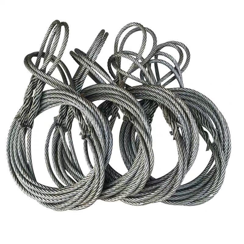
In heavy lifting operations where load geometry is irregular, contact surfaces are sensitive, or rigging configurations must adapt rapidly to site conditions, the grommet sling delivers a structural and operational advantage that conventional single-leg or multi-leg slings cannot easily replicate. Its continuous-loop architecture eliminates termination points as potential failure nodes, distributes tension across multiple wire strands simultaneously, and conforms naturally to the contours of complex loads.
For procurement engineers and rigging managers operating in marine, offshore, and heavy industrial sectors, selecting the right sling type is a risk-management decision as much as a cost decision. A misspecified sling introduces load imbalance, accelerated wear, and regulatory non-compliance — all of which carry measurable financial and safety consequences. This article examines the structural logic behind grommet sling design, maps its performance parameters to real-world application requirements, and outlines the compliance framework that governs its use in certified lifting operations. The goal is to provide a decision-making framework that supports confident procurement and operationally sound deployment.
1. What Makes a Grommet Sling Structurally Different from Standard Slings
1.1 Continuous-Loop Construction & Core Architecture
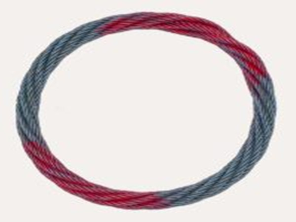
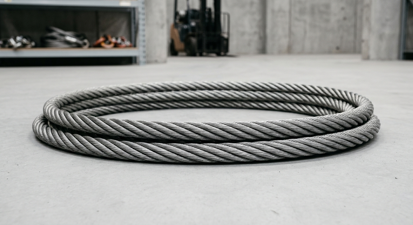
The defining characteristic of a grommet sling is its endless-loop formation — a structure assembled by laying a single wire rope strand continuously around a core until a closed, seamless loop is formed. Unlike a conventional sling, which has two discrete end terminations (swaged ferrules, spelter sockets, or mechanical splices), the grommet has no end fittings. This matters because terminations are statistically the most stress-concentrated zones in any wire rope assembly. By eliminating them, the grommet sling removes the primary mechanical weak point from the load path.
The internal construction typically follows a 6×36 IWRC (Independent Wire Rope Core) or 6×19 classification, wound in a specific lay direction to maintain strand stability under cyclic loading. The IWRC provides a rigid central support that resists crushing forces — a critical property when the sling is used in choker hitch configurations where the rope bends sharply around itself. The result is a component with inherent load path redundancy: if a surface wire sustains localized damage, the remaining wires in the strand continue to carry load, providing a measurable safety margin before structural integrity is compromised.
1.2 How the Design Translates to Load Distribution Advantage
Because the grommet sling is a closed loop, it can be rigged to contact a load at multiple points simultaneously — wrapped around structural members, threaded through lifting lugs, or configured in a basket hitch beneath a load’s center of gravity. This multi-point contact geometry produces what rigging engineers refer to as a “cradle effect”: the load is cradled by the sling’s curvature rather than suspended from discrete attachment points.
The practical consequence is a significant reduction in peak stress concentration at any single contact zone. For loads with irregular geometry — subsea equipment housings, fabricated structural modules, machined industrial components with surface-finish requirements — this distributed contact prevents localized deformation and surface damage. It also improves load stability during the lift, reducing the pendulum effect that can develop when a load is suspended from a single vertical axis. For high-value or precision-machined components, this mechanical behavior directly reduces the risk of costly damage.
2. Technical Specifications & Performance Parameters
The table below summarizes representative grommet sling specifications across common diameter ranges. Actual WLL values are configuration-dependent and must be verified against the manufacturer’s load chart and applicable standard.
| Sling Diameter (mm) | WLL — Straight Lift (tonnes) | Construction Type | Min. Breaking Force (kN) | Sling Factor (Basket, 60°) | Applicable Standard |
|---|---|---|---|---|---|
| 16 | 2.0 | 6×19 IWRC | 196 | 1.73 | EN 13414-2 |
| 22 | 4.0 | 6×36 IWRC | 392 | 1.73 | EN 13414-2 |
| 32 | 8.5 | 6×36 IWRC | 834 | 1.73 | ASME B30.9 |
| 44 | 16.0 | 6×36 IWRC | 1,570 | 1.73 | EN 13414-2 / DNV |
| 56 | 26.0 | 6×36 IWRC | 2,550 | 1.73 | DNV GL / LR |
2.1 Key Rating Variables: WLL, Sling Factor & D/d Ratio
Working Load Limit is the maximum mass a sling may lift under a specified configuration, calculated by dividing the minimum breaking force by the design factor (typically 5:1 under EN 13414 for wire rope slings). However, WLL is not a fixed value — it is configuration-dependent. As the sling angle relative to vertical increases, the tension in each leg of the sling increases proportionally. At a 60° included angle, the effective WLL per leg reduces to approximately 87% of the straight-lift rating. At 120°, it drops to 50%. Rigging managers must apply the correct sling factor for every on-site configuration.
The D/d ratio — the ratio of the bend diameter (D) to the wire rope diameter (d) — governs how much bending fatigue the sling accumulates at each use cycle. EN 13414 specifies minimum D/d ratios for different hitch types; for choker hitches, the minimum is typically 10:1. Operating below this threshold accelerates wire fatigue and dramatically shortens service life. Compliance with D/d requirements is therefore both a safety obligation and a total-cost-of-ownership consideration.
2.2 Material & Finish Options for Harsh Environments
Standard grommet slings are manufactured from ungalvanized high-carbon steel wire, suitable for controlled industrial environments. For marine and offshore applications where salt spray, humidity, and immersion are operational realities, hot-dip galvanized wire provides a zinc coating that significantly retards surface corrosion. Galvanization does introduce a marginal reduction in rope flexibility and a slight decrease in fatigue resistance under tight-bend cycling, which must be factored into D/d ratio calculations.
For subsea deployment or applications involving chemical exposure, stainless steel wire rope (typically AISI 316) offers superior corrosion resistance without the flexibility compromise of galvanization. The trade-off is cost: stainless steel grommet slings carry a significant price premium and are specified only where the environmental exposure justifies the investment.
3. Compliance Standards & Certification Requirements
3.1 Governing Standards for Marine & Offshore Use
The two primary standards governing wire rope grommet slings are EN 13414-2 (Europe) and ASME B30.9 (North America). EN 13414-2 specifies design factors, WLL calculation methods, marking requirements, and test procedures for wire rope slings, including grommets. ASME B30.9 addresses similar parameters within the US regulatory framework.
For offshore energy projects — oil and gas platforms, floating production units, offshore wind installations — third-party certification from classification societies is typically mandatory. DNV GL and Lloyd’s Register are the most widely recognized certification bodies. Their approval process requires factory audits, material traceability documentation, proof load testing at 2× WLL, and issuance of a certificate of conformity that accompanies the sling throughout its service life. Projects operating under NORSOK or IMCA guidelines will specify these certification pathways explicitly in their lifting equipment procurement standards.
3.2 Inspection, Traceability & Documentation Obligations
Every certified grommet sling must carry permanent identification: a unique serial number, WLL, construction type, and applicable standard reference. This traceability chain connects the physical sling to its material test certificate, proof load test record, and inspection history.
Periodic inspection intervals depend on usage intensity and environmental exposure. LEEA (Lifting Equipment Engineers Association) guidance and EN 13155 recommend formal inspection at minimum every 12 months, with pre-use visual checks before every lift. Mandatory discard criteria under EN 13414 include: wire breaks exceeding 10% of the total number of wires in any length equal to 8× the rope diameter; visible kinking, crushing, or birdcaging; corrosion reducing the rope diameter by more than 7%; and any evidence of heat damage or arc strikes. Slings failing any single criterion must be removed from service immediately, regardless of remaining service life.
4. Application Scenarios & Commercial Value in Heavy Lifting Operations
4.1 Marine, Offshore & Subsea Lifting Use Cases
Grommet slings are the preferred rigging element for several high-criticality lift categories. In offshore platform construction, they are used to rig structural modules — topsides sections, deck panels, and equipment skids — where load weights regularly exceed 50 tonnes and lift geometry requires a balanced, multi-point cradle configuration. The sling’s ability to be repositioned around structural members without fixed-length constraints gives riggers flexibility that pre-terminated slings cannot provide.
In subsea equipment deployment, galvanized or stainless steel grommets are used to lower ROV frames, pipeline end manifolds, and wellhead components through the splash zone. The absence of end terminations eliminates the risk of socket flooding or corrosion-driven termination failure in immersion conditions. For vessel cargo handling in port environments, basket hitch configurations using grommets allow rapid rigging of cylindrical or irregular cargo units without the need for spreader beams in many cases, reducing crane hook time and improving throughput.
4.2 Procurement & Operational ROI Considerations
The total cost of ownership for a grommet sling compares favorably to equivalent multi-leg sling assemblies when analyzed over a full service life. A grommet sling has no swaged fittings to inspect for cracking, no shackles to re-torque, and no asymmetric wear patterns between legs. Maintenance overhead is lower, and the sling’s symmetric construction means it can be rotated on the hook to distribute wear evenly across its circumference — extending service intervals.
When qualifying suppliers, procurement teams should require: proof load test certificates traceable to calibrated test equipment, material certificates to EN 10264 or equivalent, third-party certification where project specifications demand it, and documented manufacturing quality management under ISO 9001. Delivery lead time for large-diameter, certified grommets can extend to 4–8 weeks; procurement planning should account for certification processing time within project schedules.
Häufig gestellte Fragen
Q1: How do I select the correct WLL for a grommet sling when the lift angle changes on-site?
Apply the sling factor corresponding to the actual included angle at the hook. At 0° (straight vertical), the factor is 1.0. At 60° included angle, apply 0.87. At 90°, apply 0.71. At 120°, apply 0.50. Always design for the worst-case angle anticipated during the lift, and never exceed 120° included angle. Where angles are uncertain, use a spreader beam to control geometry.
Q2: What certifications should a grommet sling carry to meet offshore project requirements?
At minimum: a manufacturer’s certificate of conformity to EN 13414-2 or ASME B30.9, a proof load test certificate at 2× WLL, and material traceability documentation. For North Sea, Gulf of Mexico, or offshore wind projects, DNV GL or Lloyd’s Register third-party certification is typically specified. Confirm project-specific lifting equipment standards (NORSOK R-003, IMCA M 179) before procurement.
Q3: What are the mandatory discard criteria for a grommet sling used in repeated heavy lifting cycles?
Per EN 13414-2: discard if wire breaks exceed 10% of total wires in any 8d length; if visible kinking, crushing, birdcaging, or core protrusion is present; if corrosion reduces rope diameter by more than 7%; or if any heat damage or arc strike is identified. Discard criteria are non-negotiable — a sling meeting any single criterion must be withdrawn immediately.
Schlussfolgerung
A grommet sling is not simply an alternative rigging component — it is an engineered solution to specific load geometry, environmental, and compliance challenges that conventional slings address less efficiently. Its continuous-loop construction eliminates termination-point failure risk, its multi-point contact mechanics reduce peak stress on sensitive loads, and its adaptability across hitch configurations gives rigging teams operational flexibility that directly reduces setup time and lift complexity.
For procurement engineers, the decision framework is straightforward: match sling diameter and WLL to the maximum anticipated load at the worst-case sling angle, specify material finish to the environmental exposure class, and require certification documentation appropriate to the project’s regulatory jurisdiction. Suppliers who can provide full traceability, third-party certification, and documented quality management represent the lowest-risk procurement choice. Specified and maintained correctly, the grommet sling is one of the most reliable tools available for simplifying demanding heavy lifting operations.